How to Use TLP3555A Photorelay: Examples, Pinouts, and Specs
Introduction
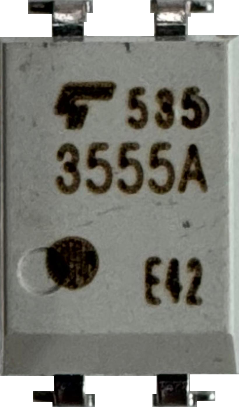
The TLP3555A is an optically isolated photorelay manufactured by Toshiba. It is designed to control high voltage and high current loads using low voltage input signals. This solid-state relay utilizes an LED and a photodetector to achieve electrical isolation between the input and output, ensuring safe and reliable operation in various applications.
The TLP3555A is widely used in:
- Industrial automation: For controlling motors, solenoids, and other high-power devices.
- Telecommunications: For signal routing and switching.
- Power management: In systems requiring high-speed switching and isolation.
Its compact design, high-speed switching capability, and robust isolation make it an ideal choice for applications requiring reliable and efficient load control.
Explore Projects Built with TLP3555A Photorelay

Explore Projects Built with TLP3555A Photorelay
Technical Specifications
Key Technical Details
| Parameter | Value |
|---|---|
| Manufacturer | Toshiba |
| Part Number | TLP3555A |
| Type | Photorelay |
| Input Type | LED (infrared) |
| Output Type | MOSFET (normally open) |
| Maximum Load Voltage | 600 V |
| Maximum Load Current | 4 A |
| Trigger LED Current (IF) | 3 mA (typical) |
| Maximum LED Current (IF) | 30 mA |
| On-State Resistance (RON) | 0.11 Ω (typical) |
| Isolation Voltage | 5000 Vrms |
| Switching Speed (Turn-On) | 3 ms (typical) |
| Switching Speed (Turn-Off) | 1 ms (typical) |
| Package Type | DIP-8 |
| Operating Temperature Range | -40°C to +110°C |
Pin Configuration and Descriptions
The TLP3555A is housed in an 8-pin DIP package. The pinout is as follows:
| Pin Number | Name | Description |
|---|---|---|
| 1 | Anode (A) | Positive terminal of the input LED. Connect to the control signal source. |
| 2 | Cathode (K) | Negative terminal of the input LED. Connect to ground. |
| 3 | NC | No connection. Leave unconnected. |
| 4 | NC | No connection. Leave unconnected. |
| 5 | Drain (D1) | Output terminal 1 of the MOSFET. Connect to the load or power source. |
| 6 | Source (S) | Common source terminal of the MOSFET. Connect to the load or ground. |
| 7 | Drain (D2) | Output terminal 2 of the MOSFET. Connect to the load or power source. |
| 8 | NC | No connection. Leave unconnected. |
Usage Instructions
How to Use the TLP3555A in a Circuit
Input Side (Control Signal):
- Connect the Anode (Pin 1) to the positive side of the control signal (e.g., a microcontroller GPIO pin).
- Connect the Cathode (Pin 2) to ground through a current-limiting resistor. The resistor value can be calculated using Ohm's law: [ R = \frac{V_{control} - V_f}{I_f} ] Where (V_{control}) is the control signal voltage, (V_f) is the forward voltage of the LED (1.2 V typical), and (I_f) is the desired forward current (e.g., 10 mA).
Output Side (Load Control):
- Connect Drain (D1, Pin 5) and Drain (D2, Pin 7) to the load or power source.
- Connect Source (S, Pin 6) to the other side of the load or ground, depending on the circuit configuration.
Power Considerations:
- Ensure the load voltage and current do not exceed the maximum ratings (600 V, 4 A).
- Use proper heat dissipation techniques if operating near the maximum current rating.
Isolation:
- The TLP3555A provides 5000 Vrms isolation between the input and output, making it suitable for high-voltage applications.
Example: Connecting to an Arduino UNO
The TLP3555A can be controlled using an Arduino UNO. Below is an example circuit and code to toggle a load using the photorelay.
Circuit Diagram
- Connect Arduino digital pin 9 to the Anode (Pin 1) of the TLP3555A through a 330 Ω resistor.
- Connect the Cathode (Pin 2) to Arduino GND.
- Connect the load (e.g., a 12 V motor) between the Drain (D1, Pin 5) and a 12 V power source.
- Connect the Source (S, Pin 6) to the ground of the 12 V power source.
Arduino Code
// TLP3555A Photorelay Control Example
// This code toggles the photorelay on and off every second.

const int relayPin = 9; // Pin connected to the TLP3555A Anode

void setup() {
  pinMode(relayPin, OUTPUT); // Set relayPin as an output
}

void loop() {
  digitalWrite(relayPin, HIGH); // Turn on the photorelay
  delay(1000);                 // Wait for 1 second
  digitalWrite(relayPin, LOW);  // Turn off the photorelay
  delay(1000);                 // Wait for 1 second
}
Best Practices
- Use a current-limiting resistor on the input side to protect the LED.
- Avoid exceeding the maximum load voltage and current ratings.
- Ensure proper heat dissipation when operating at high currents.
- Verify the isolation voltage requirements in your application to ensure safe operation.
Troubleshooting and FAQs
Common Issues and Solutions
| Issue | Possible Cause | Solution |
|---|---|---|
| Photorelay does not turn on | Insufficient input current | Check the current-limiting resistor value and ensure the control signal provides enough current. |
| Load does not operate correctly | Exceeding maximum load ratings | Verify that the load voltage and current are within the specified limits. |
| Excessive heat generation | High load current or poor heat dissipation | Use a heatsink or improve ventilation around the component. |
| No isolation between input and output | Incorrect wiring or damaged component | Verify the wiring and replace the TLP3555A if necessary. |
FAQs
Can the TLP3555A be used with AC loads?
- Yes, the TLP3555A can control AC loads, but ensure the load voltage and current are within the specified limits.
What is the maximum switching frequency?
- The TLP3555A has a typical turn-on time of 3 ms and turn-off time of 1 ms, making it suitable for low to moderate switching frequencies.
Is additional isolation required for high-voltage applications?
- The TLP3555A provides 5000 Vrms isolation, which is sufficient for most applications. However, additional isolation may be required for extremely high-voltage systems.
Can I use the TLP3555A with a 3.3 V control signal?
- Yes, as long as the forward current of the LED is sufficient (e.g., 3 mA typical). Adjust the current-limiting resistor accordingly.
This concludes the documentation for the TLP3555A Photorelay. For further details, refer to the official Toshiba datasheet.