How to Use AC SPD: Examples, Pinouts, and Specs
Introduction
An AC Surge Protective Device (SPD) is designed to protect electrical equipment from voltage spikes and surges in alternating current (AC) systems. It acts as a safeguard by diverting excess voltage away from connected devices, ensuring their longevity and reliability. SPDs are commonly used in residential, commercial, and industrial settings to protect sensitive electronics, appliances, and critical infrastructure from transient overvoltages caused by lightning strikes, power grid fluctuations, or switching operations.
Explore Projects Built with AC SPD

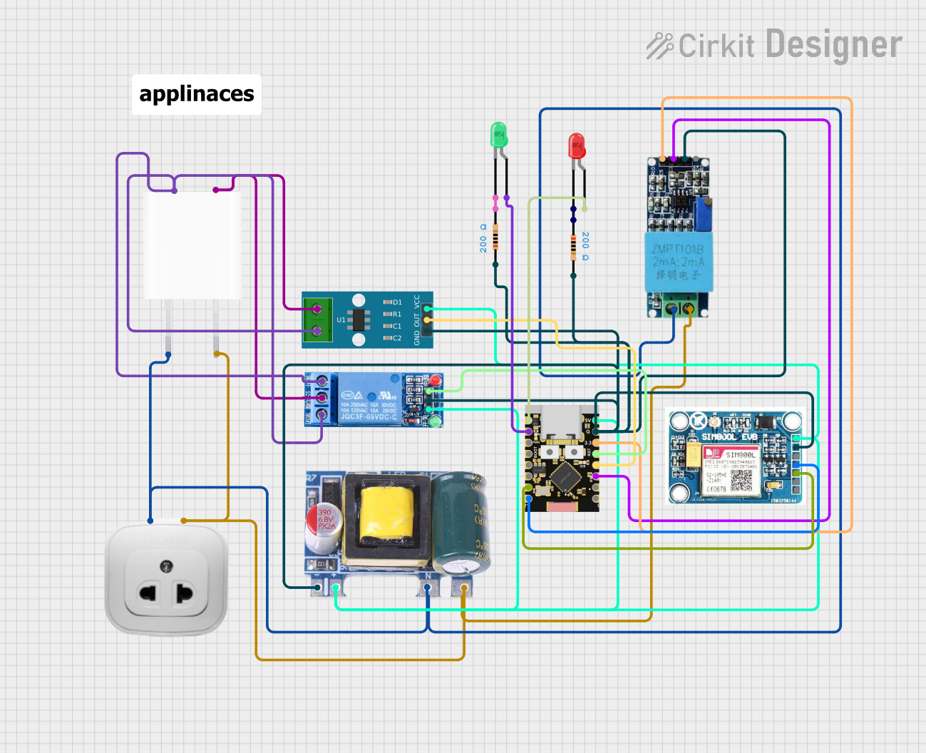
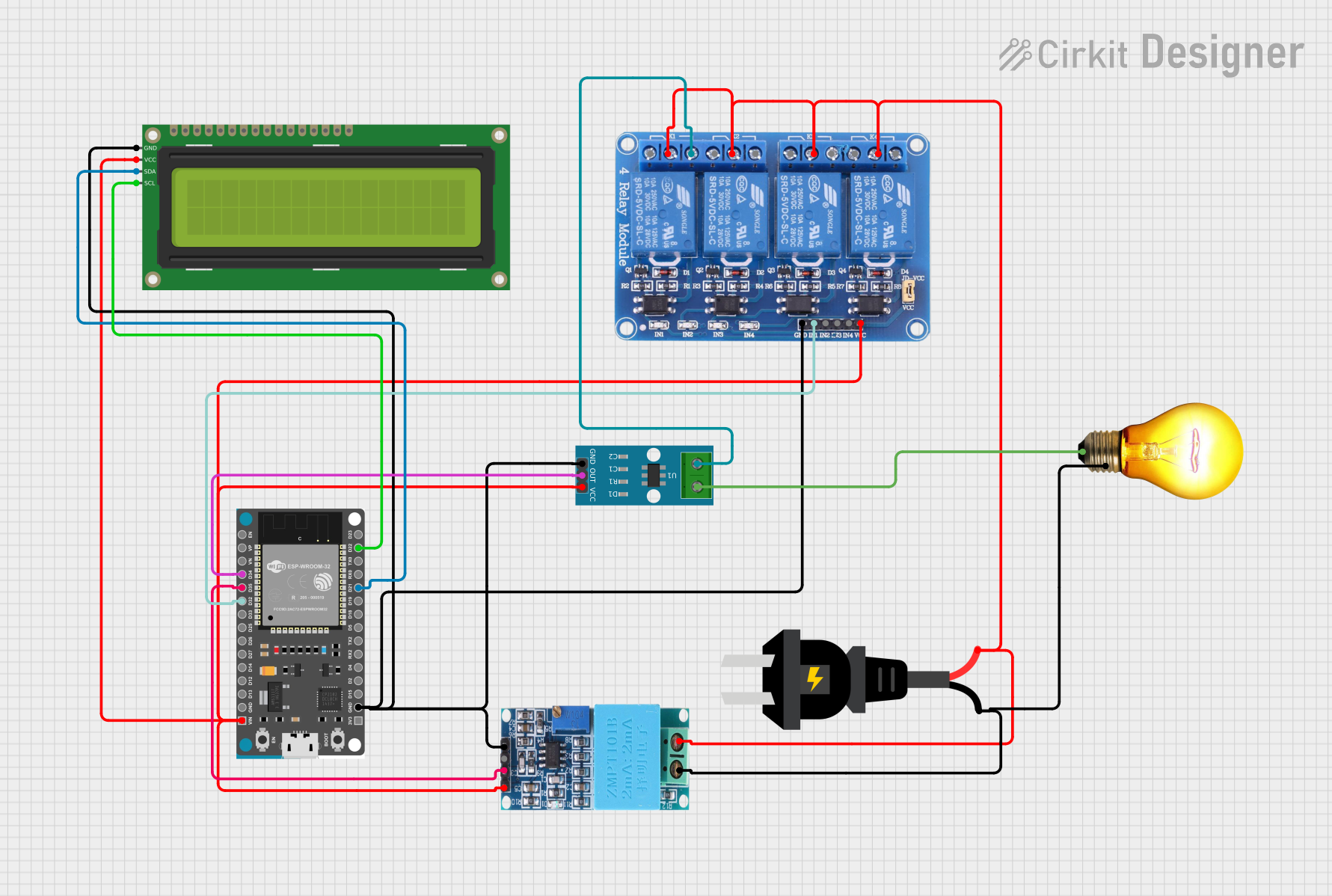
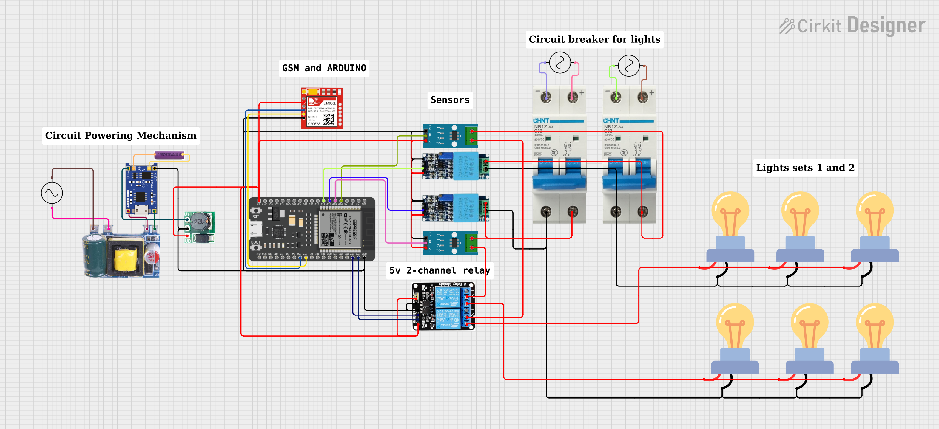
Explore Projects Built with AC SPD
Common Applications and Use Cases
- Protection of home appliances such as refrigerators, TVs, and air conditioners.
- Safeguarding industrial equipment like motors, PLCs, and sensors.
- Ensuring the reliability of data centers and IT infrastructure.
- Shielding renewable energy systems, such as solar inverters, from surges.
- Protecting electrical panels and distribution boards in buildings.
Technical Specifications
Key Technical Details
| Parameter | Value/Range |
|---|---|
| Nominal Voltage (Un) | 120V, 230V, 400V AC (varies by model) |
| Maximum Continuous Voltage (Uc) | 275V AC, 320V AC, or higher |
| Surge Current Capacity (Imax) | 10kA to 100kA (depending on model) |
| Voltage Protection Level (Up) | ≤ 1.5kV to ≤ 2.5kV |
| Response Time | < 25 nanoseconds |
| Operating Temperature Range | -40°C to +85°C |
| Enclosure Rating | IP20 to IP65 (varies by model) |
| Standards Compliance | IEC 61643-11, UL 1449 |
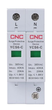
Pin Configuration and Descriptions
AC SPDs typically have a simple terminal configuration for easy integration into electrical systems. Below is a general description of the terminals:
| Terminal Name | Description |
|---|---|
| L (Line) | Connects to the live wire of the AC system. |
| N (Neutral) | Connects to the neutral wire of the AC system. |
| PE (Earth) | Connects to the protective earth/ground wire. |
Usage Instructions
How to Use the Component in a Circuit
- Identify the Installation Point: Install the AC SPD as close as possible to the equipment or distribution board you want to protect.
- Wiring:
- Connect the L (Line) terminal to the live wire of the AC system.
- Connect the N (Neutral) terminal to the neutral wire.
- Connect the PE (Earth) terminal to the ground wire for proper surge diversion.
- Mounting:
- Use a DIN rail or screw mounting (depending on the SPD model) to secure the device in place.
- Ensure the SPD is installed in a well-ventilated area to prevent overheating.
- Testing:
- After installation, test the SPD using a surge tester or multimeter to ensure proper functionality.
- Periodically inspect the SPD for wear or damage, especially after a surge event.
Important Considerations and Best Practices
- Voltage Rating: Ensure the SPD's nominal voltage (Un) matches the system voltage.
- Grounding: Proper grounding is critical for the SPD to function effectively. Verify that the earth connection has low impedance.
- Coordination: For multi-level protection, use Type 1 SPDs at the main distribution board and Type 2 or Type 3 SPDs closer to sensitive equipment.
- Replacement: SPDs degrade over time due to repeated surge events. Replace the device if the status indicator shows failure or after a significant surge.
Example: Connecting an AC SPD to an Arduino UNO
While AC SPDs are not directly connected to microcontrollers like Arduino, they can protect the power supply feeding the Arduino. Below is an example of how to integrate an SPD into a circuit powering an Arduino UNO:
// Example: Arduino UNO powered by an AC system protected by an SPD
// Note: This code assumes the Arduino is powered via a 5V DC adapter
// connected to an AC system protected by the SPD.

// No direct code is required for the SPD itself, as it operates passively.
// Ensure the SPD is installed on the AC line supplying the adapter.

// Example Arduino code to blink an LED
void setup() {
  pinMode(13, OUTPUT); // Set pin 13 as an output for the onboard LED
}

void loop() {
  digitalWrite(13, HIGH); // Turn the LED on
  delay(1000);            // Wait for 1 second
  digitalWrite(13, LOW);  // Turn the LED off
  delay(1000);            // Wait for 1 second
}
Troubleshooting and FAQs
Common Issues and Solutions
| Issue | Possible Cause | Solution |
|---|---|---|
| SPD not functioning after a surge | SPD has reached end-of-life due to wear | Replace the SPD with a new unit. |
| Frequent tripping of circuit breaker | Incorrect wiring or SPD overloading | Verify wiring and ensure SPD rating matches system. |
| High voltage still reaching equipment | Poor grounding or damaged SPD | Check and improve grounding; replace SPD if damaged. |
FAQs
How do I know if my SPD is working?
- Most SPDs have a status indicator (e.g., LED or mechanical flag). If the indicator shows failure, replace the SPD.
Can I use an AC SPD for DC systems?
- No, AC SPDs are designed specifically for alternating current systems. Use a DC SPD for direct current applications.
How often should I replace an SPD?
- Replace the SPD after a significant surge event or if the status indicator shows failure. Regular inspections are recommended.
Can I install an SPD myself?
- While installation is straightforward, it is recommended to have a qualified electrician perform the installation to ensure safety and compliance with local regulations.