How to Use MPU6050 Accelerometer + Gyroscope (Wokwi Compatible): Examples, Pinouts, and Specs
Introduction
The MPU6050 is a microelectromechanical system (MEMS) that combines a 3-axis accelerometer and a 3-axis gyroscope into one unit. This sensor is widely used in various applications such as motion tracking, gesture recognition, and robotics. Its compatibility with Wokwi, an online simulator for electronic projects, allows users to simulate and test their projects before actual hardware implementation.
Explore Projects Built with MPU6050 Accelerometer + Gyroscope (Wokwi Compatible)
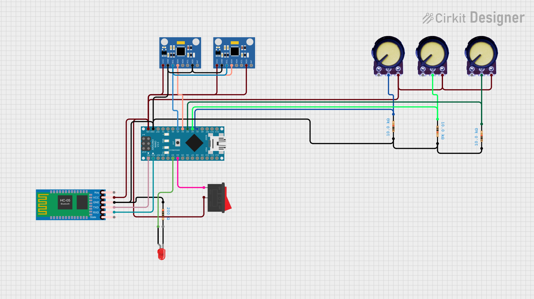
Explore Projects Built with MPU6050 Accelerometer + Gyroscope (Wokwi Compatible)
Technical Specifications
Key Technical Details
- Voltage: 2.3V to 3.4V
- Current: 3.9mA
- Operating Temperature Range: -40 to +85°C
- Sensitivity (Accelerometer): ±2g/±4g/±8g/±16g (programmable)
- Sensitivity (Gyroscope): ±250°/s, ±500°/s, ±1000°/s, ±2000°/s (programmable)
- Communication: I2C protocol
- Digital Output: 16-bit analog-to-digital conversion for each channel
- FIFO Buffer: 1024 byte
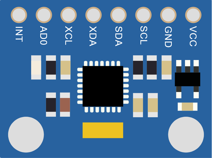
Pin Configuration and Descriptions
| Pin Name | Description |
|---|---|
| VCC | Power supply (2.3V to 3.4V) |
| GND | Ground |
| SCL | Serial Clock Line for I2C communication |
| SDA | Serial Data Line for I2C communication |
| XDA | Auxiliary Data I2C Serial Data Line |
| XCL | Auxiliary Data I2C Serial Clock Line |
| AD0 | I2C Address Select |
| INT | Interrupt Output |
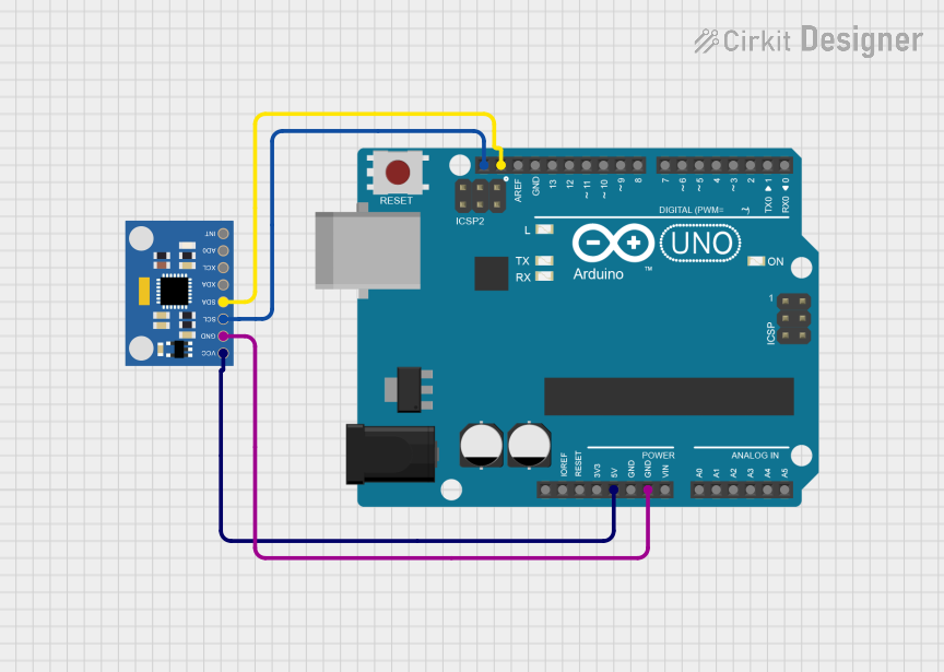
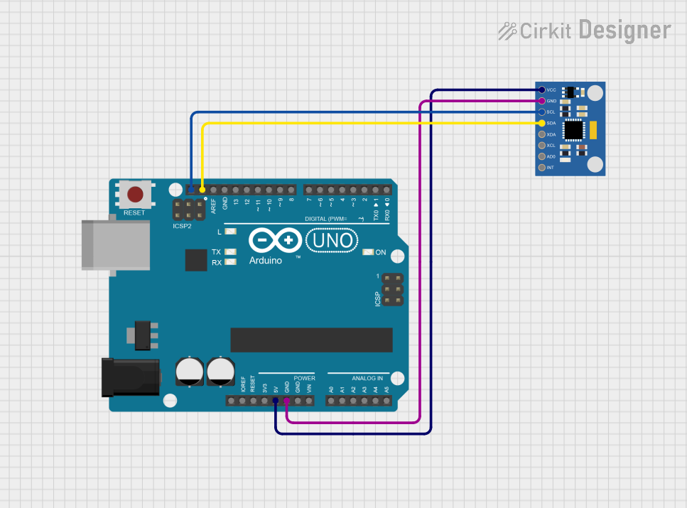
Usage Instructions
Integration into a Circuit
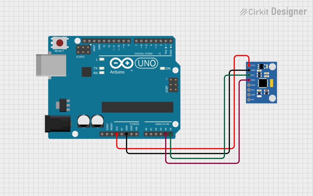
- Connect the VCC pin to the 3.3V output on your microcontroller.
- Connect the GND pin to the ground on your microcontroller.
- Connect the SCL and SDA pins to the corresponding I2C pins on your microcontroller.
- If using the interrupt feature, connect the INT pin to an external interrupt pin on your microcontroller.
- If using the auxiliary I2C bus, connect XDA and XCL to the auxiliary devices.
Important Considerations and Best Practices
- Ensure that the power supply is stable and within the specified voltage range.
- Use pull-up resistors on the SCL and SDA lines if they are not provided by the microcontroller.
- When using the sensor with a 5V microcontroller, use a level shifter for the SDA and SCL lines to avoid damaging the sensor.
- To minimize noise, keep the sensor away from motors and other sources of EMI.
- For accurate readings, calibrate the sensor for your specific application environment.
Example Code for Arduino UNO
#include <Wire.h>
#include <MPU6050.h>

MPU6050 mpu;

void setup() {
  Wire.begin();
  Serial.begin(9600);
  mpu.initialize();
  if (!mpu.testConnection()) {
    Serial.println("MPU6050 connection failed");
    while (1);
  }
  Serial.println("MPU6050 connection successful");
}

void loop() {
  mpu.getMotion6(&ax, &ay, &az, &gx, &gy, &gz);

  // Print acceleration values in m/s^2
  Serial.print("aX = "); Serial.print(ax/16384.0); Serial.print(" | ");
  Serial.print("aY = "); Serial.print(ay/16384.0); Serial.print(" | ");
  Serial.print("aZ = "); Serial.println(az/16384.0);

  // Print gyroscope values in degrees/s
  Serial.print("gX = "); Serial.print(gx/131.0); Serial.print(" | ");
  Serial.print("gY = "); Serial.print(gy/131.0); Serial.print(" | ");
  Serial.print("gZ = "); Serial.println(gz/131.0);

  delay(1000);
}
Troubleshooting and FAQs
Common Issues
- Sensor not responding: Check connections and ensure the correct I2C address is used.
- Inaccurate readings: Calibrate the sensor and ensure it's not affected by EMI.
- No data on serial monitor: Verify baud rate and ensure the Arduino IDE's serial monitor is configured correctly.
Solutions and Tips for Troubleshooting
- Use the
I2C scannersketch to confirm the device's address and connectivity. - Reset the MPU6050 and microcontroller to clear any configuration issues.
- Check for soldering issues on the MPU6050 pins if using a breakout board.
FAQs
Q: Can the MPU6050 be used with a 5V microcontroller? A: Yes, but ensure that the I2C lines are level-shifted to protect the MPU6050.
Q: How can I change the sensitivity of the accelerometer or gyroscope? A: Use the library functions to set the desired full-scale range.
Q: What is the purpose of the AD0 pin? A: The AD0 pin is used to set the LSB of the I2C address, allowing for two MPU6050s on the same bus.