How to Use DIGITAL AC WATTMETER: Examples, Pinouts, and Specs
Introduction
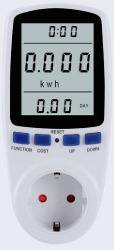
A digital AC wattmeter is an electronic device designed to measure the power consumption of alternating current (AC) electrical circuits. It provides a digital display of power in watts, enabling users to monitor energy usage and assess the efficiency of electrical devices or systems. This component is widely used in residential, commercial, and industrial applications for energy management, troubleshooting, and system optimization.
Explore Projects Built with DIGITAL AC WATTMETER
Explore Projects Built with DIGITAL AC WATTMETER
Common Applications and Use Cases
- Monitoring power consumption of household appliances.
- Measuring energy usage in industrial equipment.
- Evaluating the efficiency of electrical systems.
- Troubleshooting electrical circuits.
- Research and development in electrical engineering.
Technical Specifications
Below are the general technical specifications for a typical digital AC wattmeter. Note that specific values may vary depending on the model and manufacturer.
Key Technical Details
- Input Voltage Range: 80V AC to 260V AC
- Current Measurement Range: 0.01A to 100A (depending on the model)
- Power Measurement Range: 0.1W to 10,000W
- Accuracy: ±1% of reading
- Frequency Range: 45Hz to 65Hz
- Display Type: Digital LCD or LED
- Power Supply: Self-powered or external (varies by model)
- Operating Temperature: -10°C to 50°C
- Dimensions: Varies by model
Pin Configuration and Descriptions
The digital AC wattmeter typically has input and output terminals for connecting to the AC circuit. Below is a general description of the terminal configuration:
| Pin/Terminal | Label | Description |
|---|---|---|
| 1 | L (Line) | Connects to the live wire of the AC input. |
| 2 | N (Neutral) | Connects to the neutral wire of the AC input. |
| 3 | Load Line Out | Connects to the live wire of the load (output side). |
| 4 | Load Neutral | Connects to the neutral wire of the load (output side). |
| 5 (optional) | Ground (GND) | Provides a ground connection for safety and noise reduction (if applicable). |
Usage Instructions
How to Use the Component in a Circuit
- Safety First: Ensure the circuit is powered off before making any connections.
- Connect Input Terminals:
- Connect the live wire of the AC source to the
Lterminal. - Connect the neutral wire of the AC source to the
Nterminal.
- Connect the live wire of the AC source to the
- Connect Output Terminals:
- Connect the live wire of the load to the
Load Line Outterminal. - Connect the neutral wire of the load to the
Load Neutralterminal.
- Connect the live wire of the load to the
- Power On: Turn on the AC power source. The wattmeter will display the power consumption of the connected load.
- Read the Display: Observe the digital display to monitor the power usage in watts.
Important Considerations and Best Practices
- Voltage and Current Ratings: Ensure the wattmeter's voltage and current ratings match the circuit's specifications.
- Proper Grounding: If the wattmeter includes a ground terminal, connect it to the circuit's ground for safety.
- Avoid Overloading: Do not exceed the wattmeter's maximum current or power rating to prevent damage.
- Calibration: Periodically calibrate the wattmeter to maintain measurement accuracy.
- Environmental Conditions: Avoid using the wattmeter in extreme temperatures or high-humidity environments.
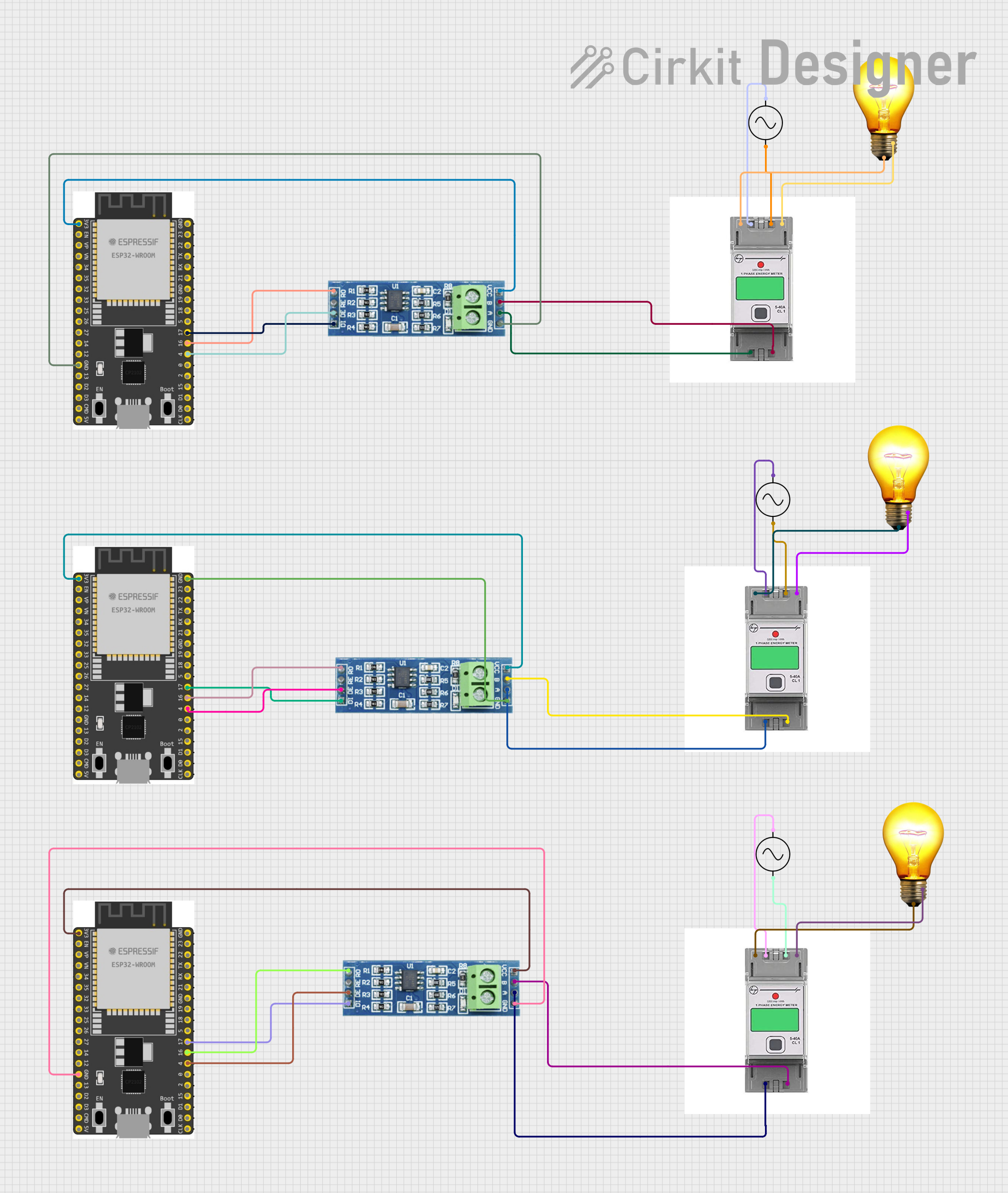
Example: Connecting to an Arduino UNO
While a digital AC wattmeter is typically a standalone device, it can be interfaced with an Arduino UNO for data logging or advanced monitoring. Below is an example of how to read wattmeter data using an Arduino UNO and a serial communication interface (if the wattmeter supports it).
// Example code to read data from a digital AC wattmeter via serial communication
// Ensure the wattmeter supports UART or similar communication protocols

#include <SoftwareSerial.h>

// Define RX and TX pins for communication with the wattmeter
SoftwareSerial wattmeterSerial(10, 11); // RX = pin 10, TX = pin 11

void setup() {
  Serial.begin(9600); // Initialize serial monitor
  wattmeterSerial.begin(9600); // Initialize wattmeter communication

  Serial.println("Digital AC Wattmeter Data Logger");
}

void loop() {
  // Check if data is available from the wattmeter
  if (wattmeterSerial.available()) {
    String wattmeterData = wattmeterSerial.readStringUntil('\n'); // Read data line
    Serial.print("Wattmeter Reading: ");
    Serial.println(wattmeterData); // Display data on serial monitor
  }

  delay(1000); // Wait 1 second before the next read
}
Note: The above code assumes the wattmeter supports serial communication. Refer to the wattmeter's datasheet for specific communication protocols and commands.
Troubleshooting and FAQs
Common Issues Users Might Face
No Display or Incorrect Readings:
- Cause: Loose connections or incorrect wiring.
- Solution: Double-check all connections and ensure proper wiring as per the pin configuration.
Overload Error:
- Cause: The connected load exceeds the wattmeter's maximum current or power rating.
- Solution: Reduce the load to within the wattmeter's specified range.
Flickering Display:
- Cause: Unstable power supply or electrical noise.
- Solution: Use a stable power source and ensure proper grounding.
Inaccurate Measurements:
- Cause: Calibration drift or environmental factors.
- Solution: Recalibrate the wattmeter and ensure it is used within the specified temperature range.
Solutions and Tips for Troubleshooting
- Verify Connections: Ensure all terminals are securely connected and match the circuit diagram.
- Check Specifications: Confirm that the wattmeter's voltage, current, and power ratings are suitable for the application.
- Inspect the Circuit: Look for any faults or issues in the connected AC circuit.
- Consult the Datasheet: Refer to the wattmeter's datasheet for detailed troubleshooting steps and technical support.
By following this documentation, users can effectively utilize a digital AC wattmeter for accurate power measurement and energy monitoring.