How to Use RJ45 8-Pin Breakout Board Kit: Examples, Pinouts, and Specs
Introduction
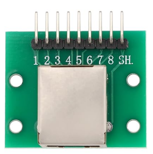
The Teansic RJ45 8-Pin Breakout Board Kit is a versatile tool designed to simplify prototyping and testing with RJ45 connectors. This breakout board provides easy access to the individual pins of an RJ45 Ethernet connector, making it ideal for applications involving Ethernet communication, custom network setups, or hardware debugging. The kit is particularly useful for engineers, hobbyists, and students working on networking projects or interfacing Ethernet-enabled devices.
Explore Projects Built with RJ45 8-Pin Breakout Board Kit
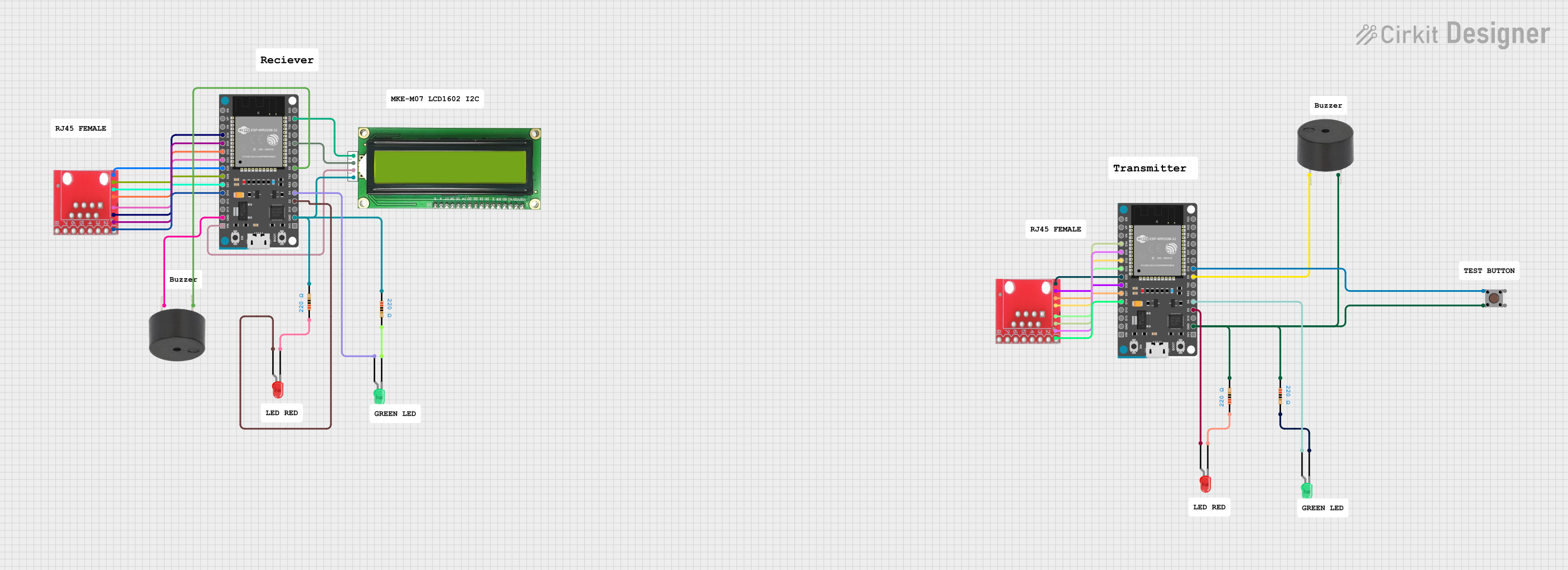

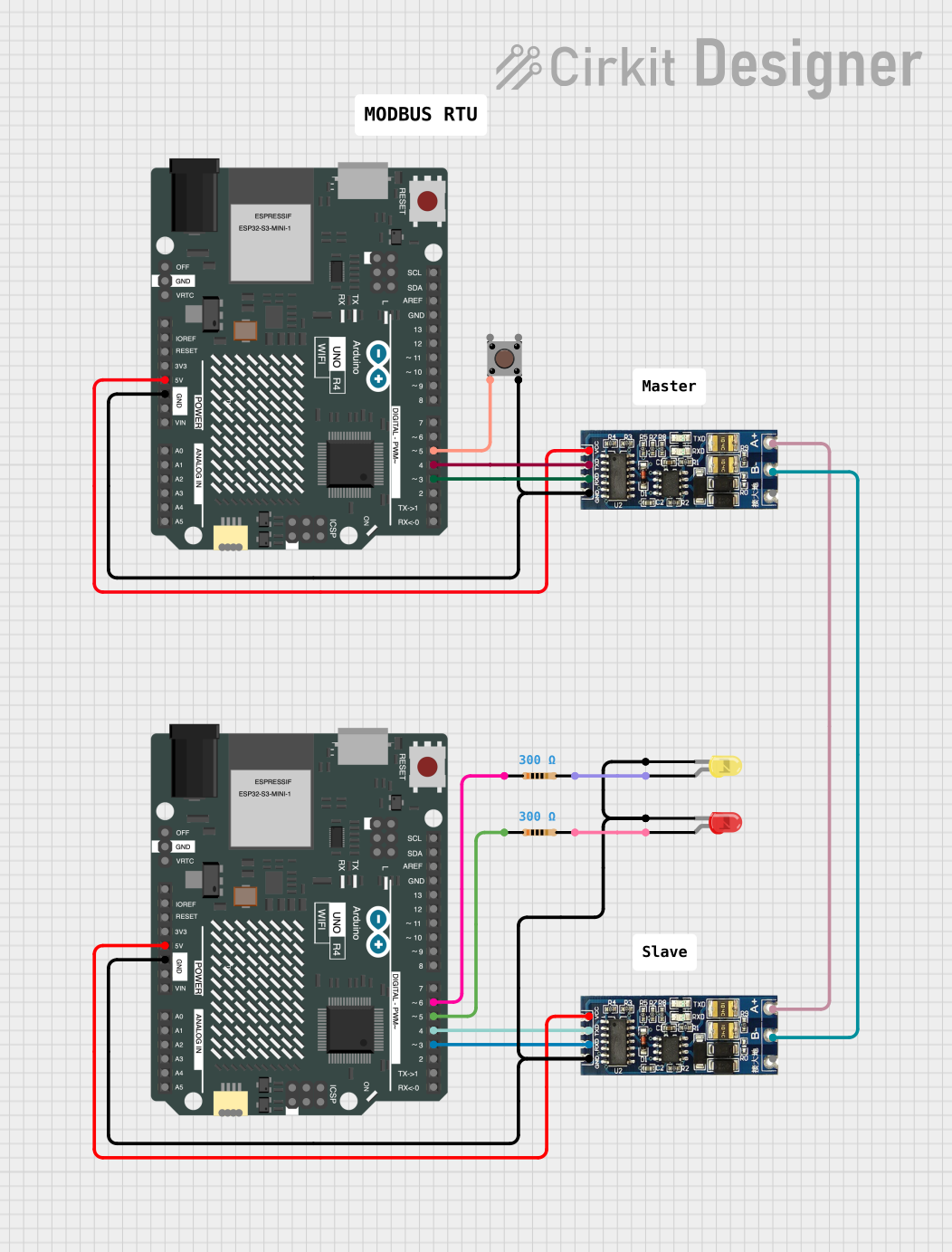
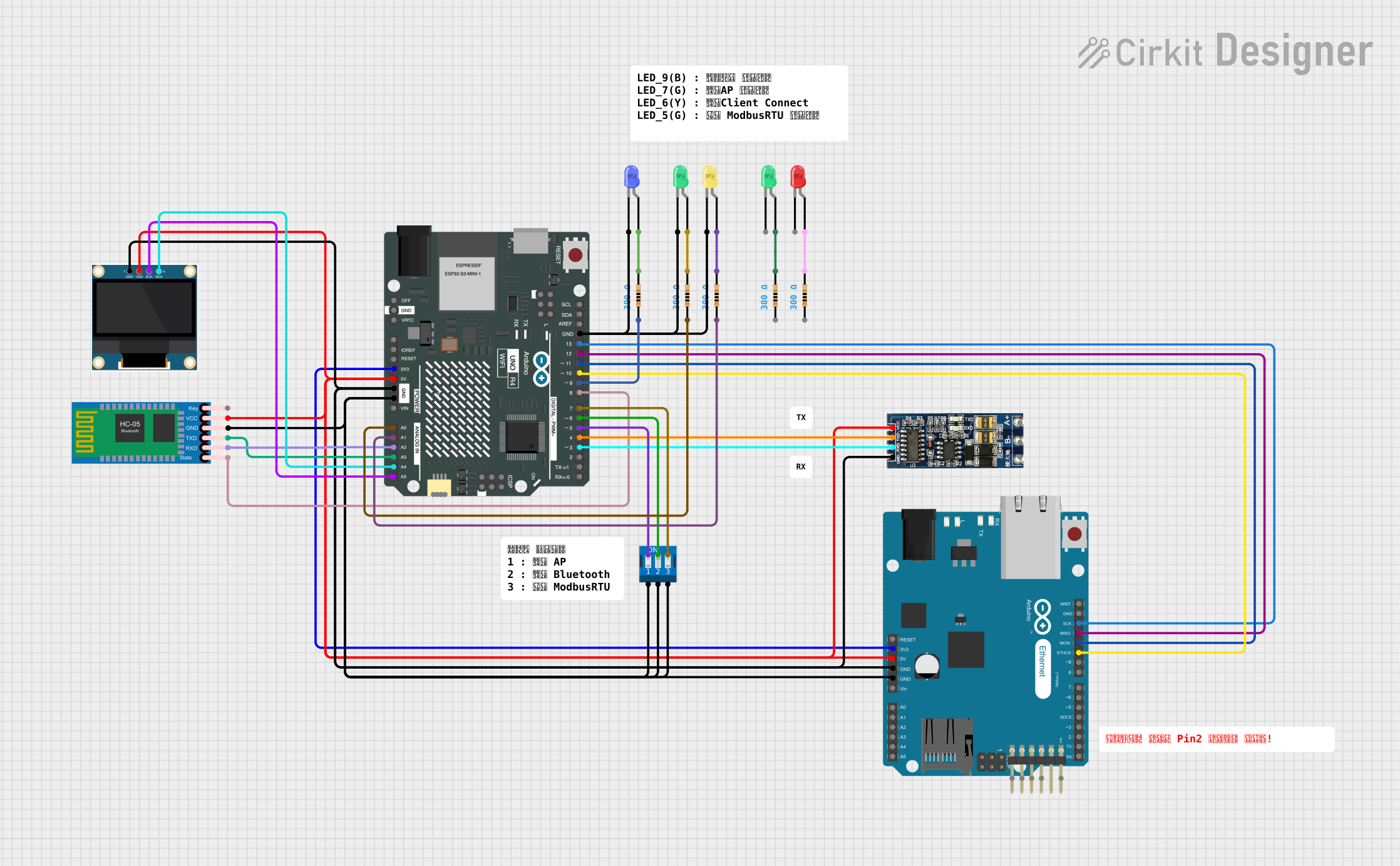
Explore Projects Built with RJ45 8-Pin Breakout Board Kit
Common Applications and Use Cases
- Prototyping Ethernet-based communication systems
- Debugging and testing Ethernet hardware
- Custom network wiring and signal analysis
- Educational projects involving Ethernet protocols
- Interfacing microcontrollers (e.g., Arduino, Raspberry Pi) with Ethernet modules
Technical Specifications
The following are the key technical details of the Teansic RJ45 8-Pin Breakout Board Kit:
| Specification | Details |
|---|---|
| Connector Type | RJ45 (8P8C) Female Socket |
| PCB Dimensions | 50mm x 25mm x 1.6mm |
| Pin Count | 8 pins (1 to 8) + 2 additional GND pins |
| Voltage Rating | 3.3V to 5V (compatible with most microcontrollers) |
| Current Rating | Up to 1A per pin |
| PCB Material | FR4, 1.6mm thickness |
| Mounting Options | Through-hole solder pads and screw holes for secure mounting |
| Additional Features | Labeled pins for easy identification, gold-plated contacts for durability |
Pin Configuration and Descriptions
The RJ45 breakout board maps the 8 pins of the RJ45 connector to labeled solder pads or headers. Below is the pinout:
| RJ45 Pin | Breakout Label | Description |
|---|---|---|
| 1 | TX+ | Transmit Data Positive |
| 2 | TX- | Transmit Data Negative |
| 3 | RX+ | Receive Data Positive |
| 4 | NC | Not Connected (used in some standards) |
| 5 | NC | Not Connected (used in some standards) |
| 6 | RX- | Receive Data Negative |
| 7 | NC | Not Connected (used in some standards) |
| 8 | NC | Not Connected (used in some standards) |
| GND | GND | Ground |
Note: The pinout follows the T568B Ethernet wiring standard. Ensure compatibility with your application.
Usage Instructions
How to Use the Component in a Circuit
Connect the RJ45 Cable:
- Plug an Ethernet cable into the RJ45 female socket on the breakout board.
Access Individual Pins:
- Use the labeled solder pads or headers to connect the breakout board to your circuit. For example:
- TX+ and TX- for transmitting data
- RX+ and RX- for receiving data
- GND for ground connection
- Use the labeled solder pads or headers to connect the breakout board to your circuit. For example:
Power the Circuit:
- Ensure the breakout board is connected to a compatible voltage source (3.3V or 5V) if required by your application.
Interfacing with Microcontrollers:
- Use jumper wires to connect the breakout board to a microcontroller (e.g., Arduino UNO). Below is an example of interfacing the breakout board with an Arduino UNO for basic Ethernet communication.
Example Arduino Code
#include <SPI.h>
#include <Ethernet.h>

// MAC address and IP address for the Ethernet shield
byte mac[] = { 0xDE, 0xAD, 0xBE, 0xEF, 0xFE, 0xED };
IPAddress ip(192, 168, 1, 177);

// Initialize the Ethernet server on port 80
EthernetServer server(80);

void setup() {
  // Start the Ethernet connection
  Ethernet.begin(mac, ip);

  // Start the server
  server.begin();

  // Print the IP address to the Serial Monitor
  Serial.begin(9600);
  Serial.print("Server is at ");
  Serial.println(Ethernet.localIP());
}

void loop() {
  // Listen for incoming clients
  EthernetClient client = server.available();
  if (client) {
    Serial.println("New client connected");
    // Send a simple HTTP response
    client.println("HTTP/1.1 200 OK");
    client.println("Content-Type: text/html");
    client.println();
    client.println("<h1>Hello from RJ45 Breakout Board!</h1>");
    client.stop(); // Close the connection
  }
}
Important: Ensure the Ethernet shield or module is properly connected to the RJ45 breakout board. The MAC and IP addresses should be configured according to your network.
Important Considerations and Best Practices
- Check Pinout: Verify the pinout of your Ethernet cable and ensure it matches the breakout board's configuration.
- Avoid Overloading: Do not exceed the current rating of 1A per pin to prevent damage.
- Use Shielded Cables: For high-speed or long-distance applications, use shielded Ethernet cables to reduce interference.
- Secure Connections: Use screws or solder the breakout board to a stable surface to prevent accidental disconnections.
Troubleshooting and FAQs
Common Issues and Solutions
No Ethernet Connection Detected:
- Solution: Check the Ethernet cable and ensure it is securely connected to the RJ45 socket.
- Solution: Verify the pin connections between the breakout board and your circuit.
Intermittent Data Transmission:
- Solution: Use shielded Ethernet cables to minimize interference.
- Solution: Ensure proper grounding of the breakout board.
Incorrect Pin Mapping:
- Solution: Double-check the pinout of the breakout board and your Ethernet device. Ensure compatibility with the T568B standard.
Arduino Code Not Working:
- Solution: Verify the MAC and IP address settings in the code.
- Solution: Ensure the Ethernet library is installed and up to date.
FAQs
Q: Can this breakout board be used with Power over Ethernet (PoE)?
A: No, this breakout board does not support PoE. It is designed for standard Ethernet connections only.
Q: Is the breakout board compatible with Cat6 cables?
A: Yes, the breakout board is compatible with Cat5, Cat5e, and Cat6 Ethernet cables.
Q: Can I use this breakout board for non-Ethernet applications?
A: Yes, the breakout board can be used to access individual pins of the RJ45 connector for custom applications, such as serial communication or GPIO expansion.
Q: Does the kit include headers or connectors?
A: The kit typically includes the breakout board and may come with headers or screw terminals, depending on the package. Check the product listing for details.
By following this documentation, you can effectively use the Teansic RJ45 8-Pin Breakout Board Kit for your Ethernet and prototyping needs.