How to Use 2 x AA Battery Mount: Examples, Pinouts, and Specs
Introduction
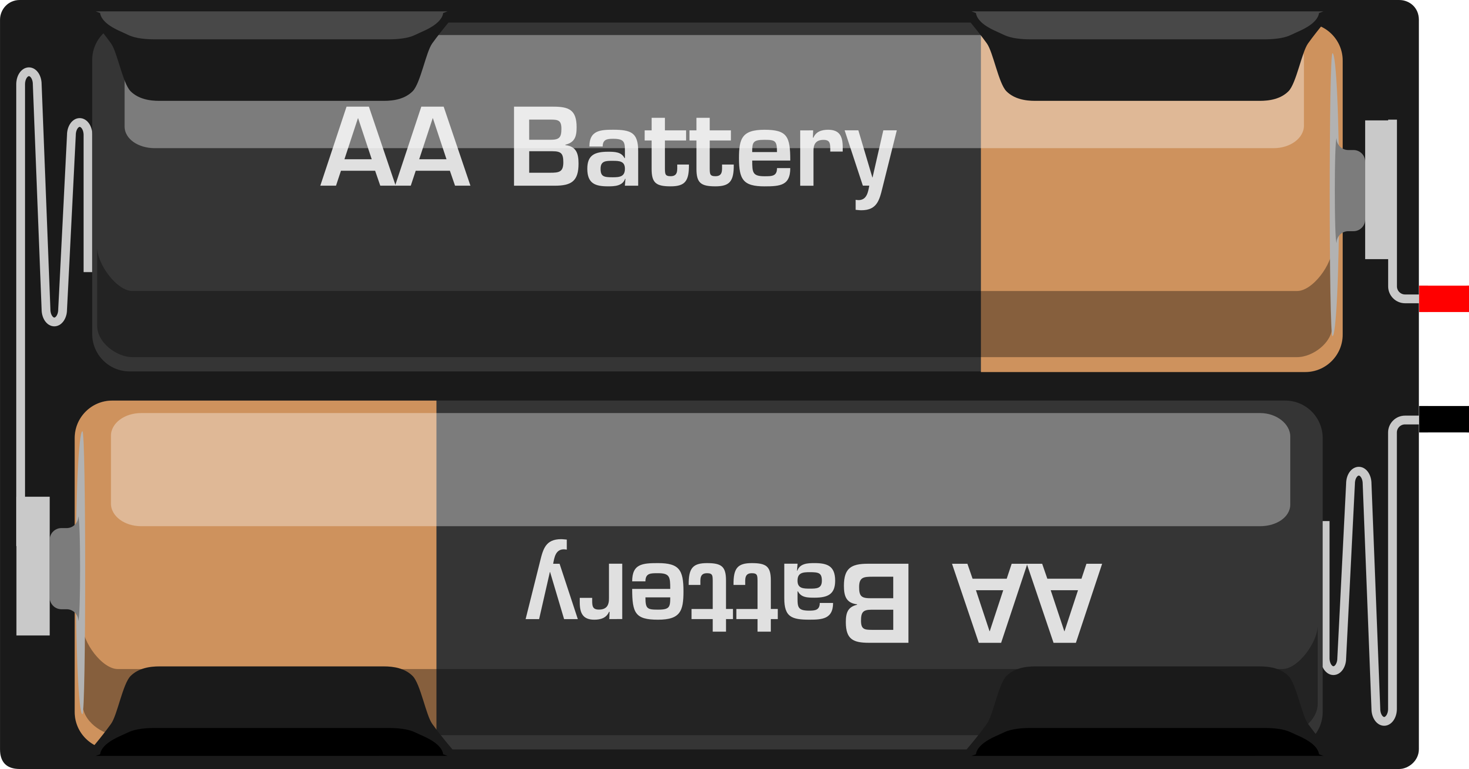
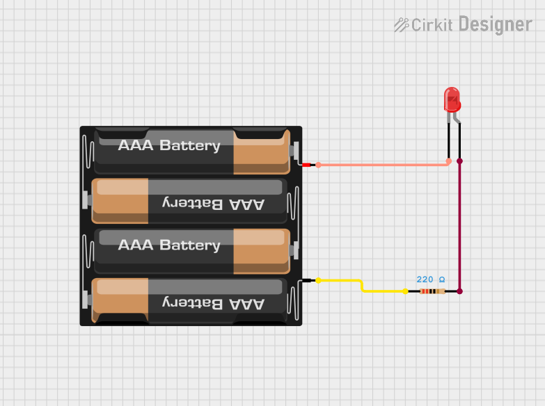
The 2 x AA Battery Mount is a simple yet essential electronic component that provides a reliable power source for various low-voltage electronic devices. It is designed to hold two AA batteries, which in series configuration can supply a nominal voltage of 3V. This battery mount is commonly used in portable devices, DIY projects, and educational electronics where a compact and replaceable power source is needed.
Explore Projects Built with 2 x AA Battery Mount
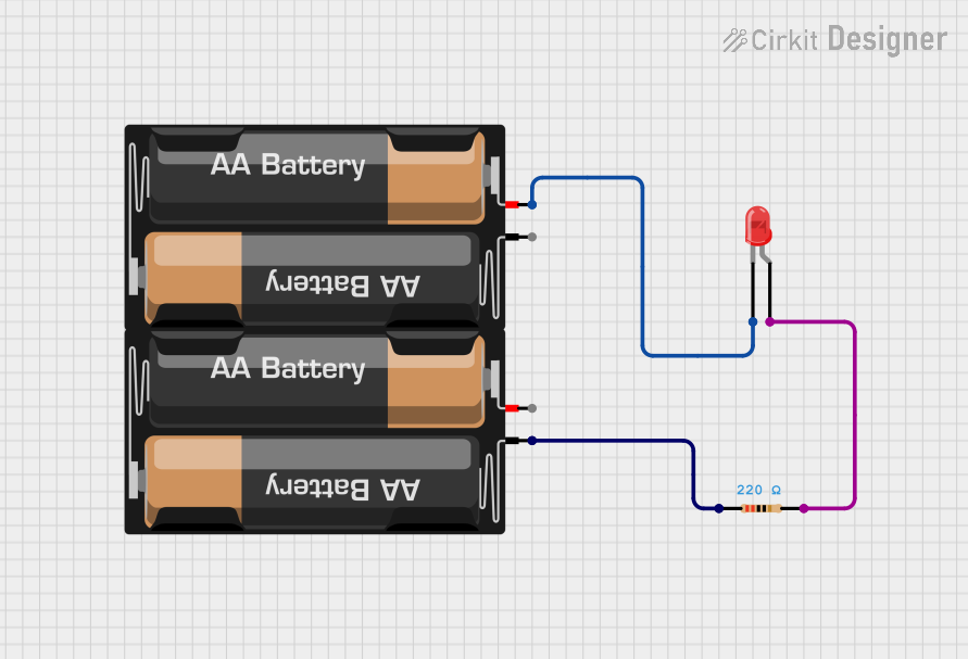
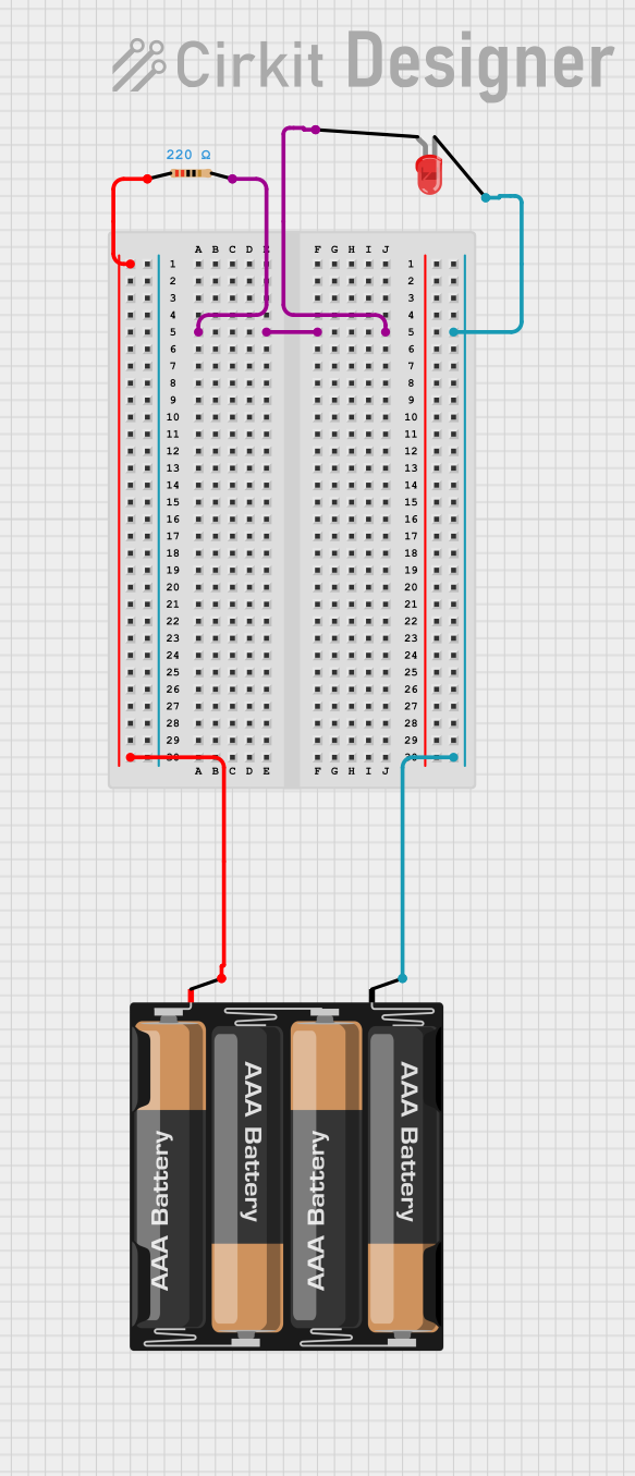
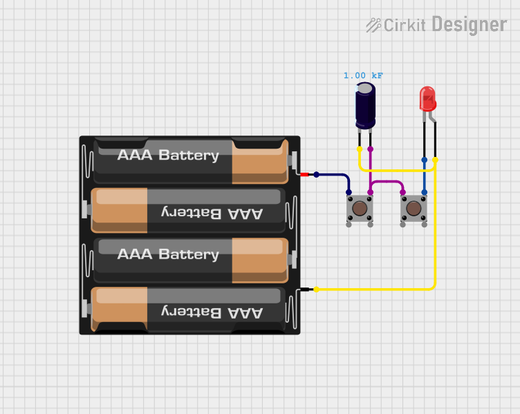
Explore Projects Built with 2 x AA Battery Mount
Common Applications and Use Cases
- Portable electronic devices
- DIY electronics projects
- Educational kits for teaching electronics
- Remote controls
- Small robotics systems
- Arduino-based circuits requiring a 3V power source
Technical Specifications
Key Technical Details
- Nominal Voltage Output: 3V (when 2 AA batteries are used)
- Maximum Current: Depends on the batteries used (typically around 1-3A for AA batteries)
- Material: Plastic (commonly ABS)
- Number of Cells: 2
- Battery Type: AA
- Mounting Type: Through-hole, adhesive backing, or slots for straps
Pin Configuration and Descriptions
| Pin Name | Description |
|---|---|
| V+ | Positive voltage output from batteries |
| V- | Ground reference from batteries |
Usage Instructions
How to Use the Component in a Circuit
Inserting Batteries:
- Ensure the batteries are inserted with the correct polarity. The positive end (+) of the battery should align with the positive terminal of the holder, and the negative end (-) with the negative terminal.
Connecting to a Circuit:
- Use the leads from the battery mount to connect to your circuit. The red wire is typically the positive (V+) and the black wire is the negative (V-).
- If soldering, ensure a good quality joint without overheating the battery mount terminals.
Mounting the Holder:
- Depending on the design, use screws, adhesive backing, or straps to secure the battery mount to your project.
Important Considerations and Best Practices
- Battery Orientation: Always double-check the orientation of the batteries before powering the circuit to prevent damage.
- Battery Replacement: Make sure the device is turned off before replacing batteries to avoid short circuits.
- Secure Mounting: Ensure the battery mount is securely attached to prevent batteries from dislodging during movement.
- Contact Cleaning: Keep the battery contacts clean for optimal performance and to prevent power interruptions.
Troubleshooting and FAQs
Common Issues Users Might Face
- Device Not Powering On: Check if the batteries are inserted correctly and if they have sufficient charge.
- Intermittent Power: Ensure that the battery contacts are clean and that the batteries are securely fitted in the mount.
- Overheating at the Terminals: This could be due to a short circuit in your device. Check your circuit for any possible shorts.
Solutions and Tips for Troubleshooting
- Battery Orientation: Reinsert the batteries with the correct polarity if the device does not power on.
- Battery Replacement: Use fresh batteries if the current ones are depleted.
- Contact Cleaning: Clean the contacts with a bit of rubbing alcohol on a cotton swab to remove any corrosion or residue.
FAQs
Q: Can I use rechargeable AA batteries with this mount? A: Yes, rechargeable AA batteries can be used as long as they are the correct size and voltage.
Q: What is the maximum voltage the battery mount can handle? A: The battery mount is designed for two AA batteries, providing a total of 3V. Do not exceed this voltage to avoid damaging your circuit.
Q: How do I know when to replace the batteries? A: When the device starts to perform poorly or stops working, it's time to check and possibly replace the batteries.
Q: Can this battery mount be used with an Arduino UNO? A: Yes, it can power an Arduino UNO, but you will need a voltage regulator or buck converter to step up the voltage to the required 5V for the Arduino UNO.
Example Code for Arduino UNO
// This example demonstrates how to use the 2 x AA Battery Mount to power an Arduino UNO
// through the Vin pin. Note that a step-up voltage regulator is required to boost the
// voltage to 5V, which is the minimum operating voltage for the Arduino UNO.

void setup() {
  // Initialize digital pin LED_BUILTIN as an output.
  pinMode(LED_BUILTIN, OUTPUT);
}

void loop() {
  // Turn the LED on (HIGH is the voltage level)
  digitalWrite(LED_BUILTIN, HIGH);
  // Wait for a second
  delay(1000);
  // Turn the LED off by making the voltage LOW
  digitalWrite(LED_BUILTIN, LOW);
   // Wait for a second
  delay(1000);
}

// Note: This code is for demonstration purposes only and assumes that you have
// the necessary step-up voltage regulator in place to provide the Arduino UNO
// with the correct operating voltage.
Remember to adhere to the 80-character line length limit for code comments, wrapping text as needed. This example code blinks the built-in LED on the Arduino UNO, which is a simple way to verify that the power supply from the 2 x AA Battery Mount is working correctly through the voltage regulator.