How to Use Pilot Lamp Green: Examples, Pinouts, and Specs
Introduction
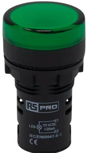
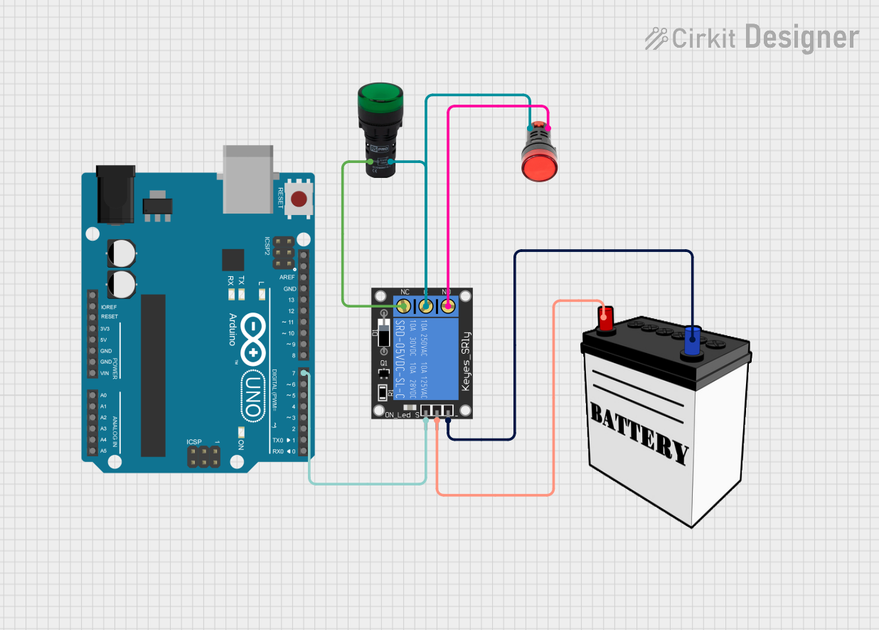
A Pilot Lamp Green is a small, low-powered indicator light commonly used in electrical circuits to provide a visual indication of the system's status. The green color of the lamp usually signifies that a device or system is operational and functioning correctly. These lamps are widely used in control panels, dashboards, and various electronic devices to signal power status, confirm functionality, or indicate the completion of a process.
Explore Projects Built with Pilot Lamp Green
Explore Projects Built with Pilot Lamp Green
Common Applications and Use Cases
- Control panels for machinery
- Power status indicators on electronic devices
- Status indication for safety and security systems
- Signal lights in automotive dashboards
- Indicators for network and communication equipment
Technical Specifications
Key Technical Details
| Specification | Value | Description |
|---|---|---|
| Rated Voltage | 12V DC | The voltage at which the lamp operates |
| Power Consumption | 0.5W | The power the lamp consumes |
| Luminous Intensity | 20 mcd (typ.) | The typical brightness of the lamp |
| Lifespan | 30,000 hours | The expected operational life |
| Operating Temp. | -20°C to +65°C | Suitable temperature range for operation |
Pin Configuration and Descriptions
| Pin Number | Description |
|---|---|
| 1 | Anode (+) |
| 2 | Cathode (-) |
Usage Instructions
How to Use the Component in a Circuit
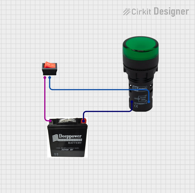
- Power Source Connection: Connect the anode (positive) pin of the Pilot Lamp Green to the positive terminal of a 12V DC power source.
- Ground Connection: Connect the cathode (negative) pin to the ground terminal of the power source.
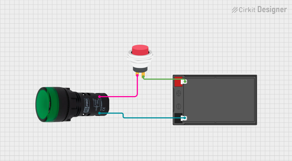
- Switch Integration (Optional): To control the lamp, insert a switch between the power source and the anode pin of the lamp.
Important Considerations and Best Practices
- Voltage Rating: Ensure that the power source does not exceed the rated voltage of 12V DC to prevent damage to the lamp.
- Current Limiting: If the power source has a higher voltage or is unregulated, use a current-limiting resistor to prevent excessive current flow.
- Heat Dissipation: Although the lamp has low power consumption, ensure there is adequate ventilation around the lamp to prevent overheating.
- Mounting: Secure the lamp firmly in place to prevent movement that could lead to wiring fatigue or disconnection.
Troubleshooting and FAQs
Common Issues Users Might Face
- Lamp Not Illuminating: Check the power supply and connections to ensure proper voltage and polarity.
- Dim Light: Verify that the power source is providing the correct voltage and that there are no voltage drops in the circuit.
- Flickering Light: Inspect the connections for any loose wires or intermittent contacts.
Solutions and Tips for Troubleshooting
- Check Connections: Ensure all connections are secure and free from corrosion.
- Measure Voltage: Use a multimeter to confirm the power supply is delivering 12V DC.
- Replace Lamp: If the lamp fails to illuminate after checking the above, consider replacing the lamp as it may have reached the end of its lifespan.
FAQs
Q: Can I use the Pilot Lamp Green with an AC power source? A: No, this lamp is designed for 12V DC power sources only.
Q: Is it necessary to use a current-limiting resistor? A: If the power source is exactly 12V DC and regulated, a resistor is not required. However, for unregulated sources, a resistor may be necessary to prevent damage.
Q: How do I know if the Pilot Lamp Green is burnt out? A: If the lamp does not illuminate when power is applied and all connections are secure, the lamp may be burnt out and require replacement.
Example Code for Arduino UNO Connection
// Define the pin connected to the Pilot Lamp Green
const int pilotLampPin = 13; // Using onboard LED pin as an example

void setup() {
  // Set the pilot lamp pin as an output
  pinMode(pilotLampPin, OUTPUT);
}

void loop() {
  // Turn on the Pilot Lamp Green
  digitalWrite(pilotLampPin, HIGH);
  delay(1000); // Keep the lamp on for 1 second

  // Turn off the Pilot Lamp Green
  digitalWrite(pilotLampPin, LOW);
  delay(1000); // Keep the lamp off for 1 second
}
Note: The above code uses the Arduino's onboard LED (pin 13) as an example. When connecting the actual Pilot Lamp Green, ensure it is connected to a suitable digital pin and powered by an external 12V DC source with appropriate current limiting if necessary.