How to Use UWB Click: Examples, Pinouts, and Specs
Introduction
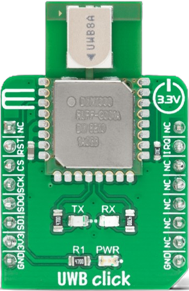
The UWB Click (Manufacturer Part ID: MIKROE-4199) is a compact module designed by Mikroe for ultra-wideband (UWB) communication. It enables precise ranging and localization capabilities, making it ideal for applications requiring high accuracy and low latency. UWB Click is widely used in IoT, smart home devices, asset tracking, and industrial automation. Its ability to measure distances with centimeter-level precision makes it a powerful tool for real-time location systems (RTLS).
Explore Projects Built with UWB Click


Explore Projects Built with UWB Click
Technical Specifications
The following table outlines the key technical details of the UWB Click module:
| Parameter | Value |
|---|---|
| Communication Protocol | SPI (Serial Peripheral Interface) |
| Operating Voltage | 3.3V |
| Power Consumption | Low power consumption in idle mode; configurable active mode power usage |
| Frequency Range | 3.1 GHz to 10.6 GHz |
| Ranging Accuracy | ±10 cm |
| Data Rate | Up to 6.8 Mbps |
| Operating Temperature | -40°C to +85°C |
| Dimensions | 25.4 mm x 25.4 mm |
Pin Configuration and Descriptions
The UWB Click module uses a standard mikroBUS™ socket for easy integration. Below is the pinout description:
| Pin | Name | Type | Description |
|---|---|---|---|
| 1 | AN | Input | General-purpose analog input |
| 2 | RST | Input | Reset pin to restart the module |
| 3 | CS | Input | SPI Chip Select |
| 4 | SCK | Input | SPI Clock |
| 5 | MISO | Output | SPI Master-In-Slave-Out |
| 6 | MOSI | Input | SPI Master-Out-Slave-In |
| 7 | PWM | Output | General-purpose PWM output |
| 8 | INT | Output | Interrupt pin for event signaling |
| 9 | GND | Ground | Ground connection |
| 10 | 3.3V | Power Supply | 3.3V power supply input |
Usage Instructions
How to Use the UWB Click in a Circuit
Hardware Setup:
- Connect the UWB Click module to a mikroBUS™ socket on a compatible development board.
- Ensure the board provides a stable 3.3V power supply.
- Use SPI-compatible pins (CS, SCK, MISO, MOSI) for communication with the host microcontroller.
Software Setup:
- Install the appropriate UWB Click library or driver from Mikroe's website.
- Configure the SPI interface on your microcontroller to match the module's settings.
Basic Circuit Example:
- Connect the UWB Click to an Arduino UNO using an adapter or shield that supports mikroBUS™.
- Ensure proper grounding and power connections.
Arduino UNO Example Code
Below is an example code snippet to initialize and communicate with the UWB Click module using SPI:
#include <SPI.h>

// Define SPI pins for Arduino UNO
#define CS_PIN 10  // Chip Select pin
#define RST_PIN 9  // Reset pin
#define INT_PIN 2  // Interrupt pin

void setup() {
  // Initialize Serial Monitor
  Serial.begin(9600);
  while (!Serial);

  // Initialize SPI
  SPI.begin();
  pinMode(CS_PIN, OUTPUT);
  pinMode(RST_PIN, OUTPUT);
  pinMode(INT_PIN, INPUT);

  // Reset the UWB Click module
  digitalWrite(RST_PIN, LOW);
  delay(100);
  digitalWrite(RST_PIN, HIGH);
  delay(100);

  Serial.println("UWB Click initialized.");
}

void loop() {
  // Example: Send a command to the UWB Click module
  digitalWrite(CS_PIN, LOW);  // Select the module
  SPI.transfer(0x01);         // Example command (replace with actual command)
  digitalWrite(CS_PIN, HIGH); // Deselect the module

  delay(1000); // Wait for 1 second
}
Important Considerations and Best Practices
- Power Supply: Ensure a stable 3.3V power supply to avoid communication errors or module damage.
- SPI Configuration: Match the SPI clock speed and mode with the UWB Click's requirements.
- Antenna Placement: For optimal performance, ensure the module's antenna is unobstructed and positioned away from metal surfaces.
- Interrupt Handling: Use the INT pin to handle events like data reception or ranging completion efficiently.
Troubleshooting and FAQs
Common Issues and Solutions
Module Not Responding:
- Verify the power supply voltage (3.3V).
- Check SPI connections and ensure proper pin mapping.
- Reset the module using the RST pin.
Inaccurate Ranging Results:
- Ensure there are no obstacles or interference in the UWB signal path.
- Verify the antenna placement and orientation.
Communication Errors:
- Check the SPI clock speed and mode configuration.
- Ensure the CS pin is toggled correctly during communication.
FAQs
Q1: Can the UWB Click be used outdoors?
A1: Yes, the UWB Click can be used outdoors, but environmental factors like obstacles and interference may affect performance.
Q2: What is the maximum range of the UWB Click?
A2: The module supports a maximum range of approximately 50 meters in ideal conditions.
Q3: Is the UWB Click compatible with 5V systems?
A3: No, the UWB Click operates at 3.3V. Use a level shifter if interfacing with a 5V system.
Q4: Can multiple UWB Click modules be used simultaneously?
A4: Yes, multiple modules can be used for multi-node localization systems, but ensure proper synchronization and channel configuration.
By following this documentation, users can effectively integrate and utilize the UWB Click module in their projects.