How to Use TM1637: Examples, Pinouts, and Specs
Introduction
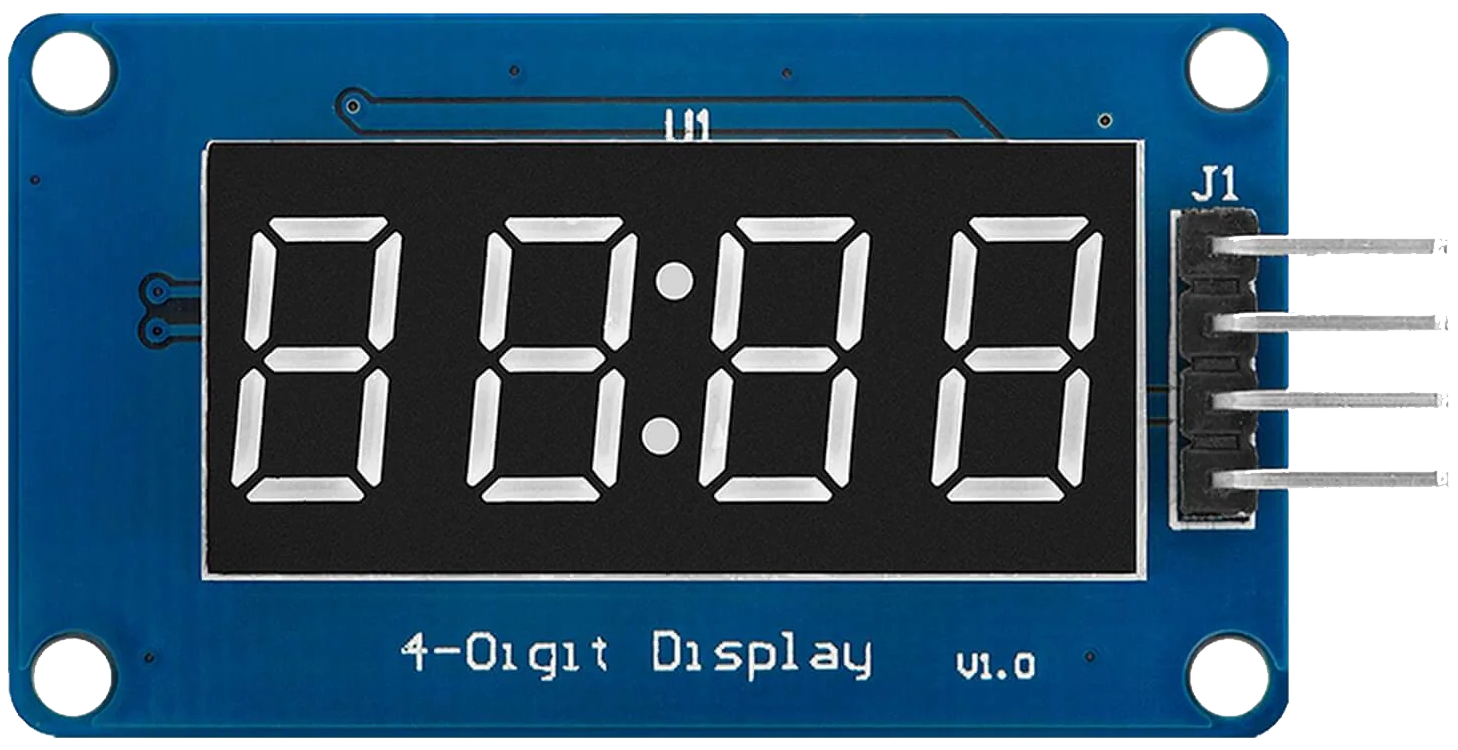
The TM1637 is a versatile 7-segment display driver capable of controlling up to 6 digits. It uses a simple two-wire interface (CLK and DIO) for communication, making it easy to integrate into microcontroller-based projects. This component is widely used in applications such as digital clocks, counters, temperature displays, and other projects requiring numeric or alphanumeric output.
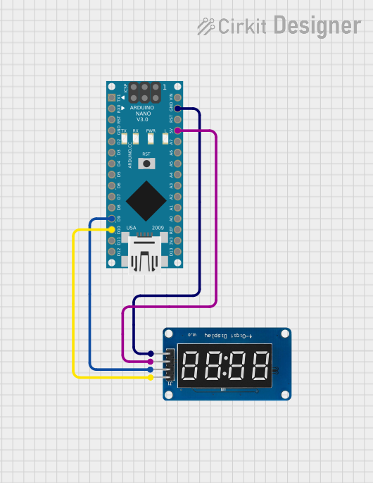
The TM1637 is particularly popular in hobbyist and educational projects due to its simplicity and compatibility with platforms like Arduino, Raspberry Pi, and other microcontrollers.
Explore Projects Built with TM1637

Explore Projects Built with TM1637
Technical Specifications
- Manufacturer: Unknown
- Part ID: TM1637
- Description: 7-segment display driver with two-wire communication
- Operating Voltage: 3.3V to 5.5V
- Operating Current: ~80mA (varies with the number of segments lit)
- Interface: Two-wire (CLK and DIO)
- Maximum Digits Controlled: 6
- Brightness Control: 8 levels (adjustable via software)
- Operating Temperature: -40°C to +85°C
Pin Configuration and Descriptions
The TM1637 typically interfaces with a 4-pin 7-segment display module. Below is the pinout:
| Pin | Name | Description |
|---|---|---|
| 1 | GND | Ground (0V reference) |
| 2 | VCC | Power supply (3.3V to 5.5V) |
| 3 | DIO | Data I/O pin for communication |
| 4 | CLK | Clock pin for communication |
Usage Instructions
How to Use the TM1637 in a Circuit
Connect the Power Supply:
- Connect the
VCCpin to a 3.3V or 5V power source. - Connect the
GNDpin to the ground of your circuit.
- Connect the
Connect the Communication Pins:
- Connect the
DIOpin to a digital I/O pin on your microcontroller. - Connect the
CLKpin to another digital I/O pin on your microcontroller.
- Connect the
Install Required Libraries (if using Arduino):
- Use the
TM1637Displaylibrary, which simplifies communication with the TM1637. - Install the library via the Arduino IDE Library Manager.
- Use the
Write the Code:
- Use the library functions to initialize the display, set brightness, and display numbers or characters.
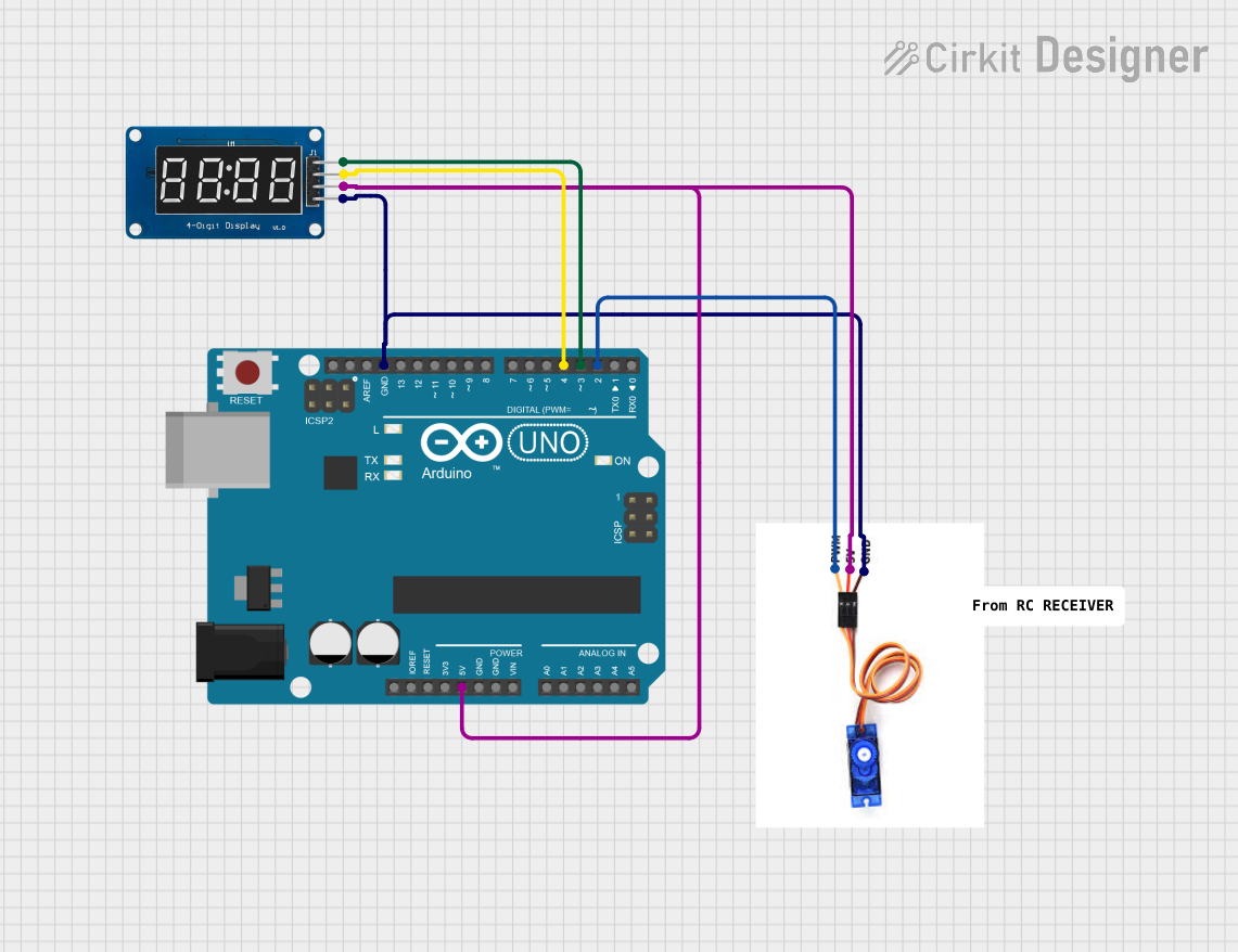
Example Code for Arduino UNO
Below is an example of how to use the TM1637 with an Arduino UNO to display a 4-digit number:
#include <TM1637Display.h>

// Define the CLK and DIO pins connected to the TM1637
#define CLK 2  // Clock pin connected to digital pin 2
#define DIO 3  // Data I/O pin connected to digital pin 3

// Create an instance of the TM1637Display class
TM1637Display display(CLK, DIO);

void setup() {
  // Set the brightness of the display (0 to 7)
  display.setBrightness(5);

  // Display a number (e.g., 1234)
  display.showNumberDec(1234);
}

void loop() {
  // No actions in the loop for this example
}
Important Considerations and Best Practices
- Power Supply: Ensure the power supply voltage is within the specified range (3.3V to 5.5V). Exceeding this range may damage the component.
- Pull-Up Resistors: The TM1637 module typically includes built-in pull-up resistors for the CLK and DIO lines. If you're using a bare TM1637 chip, you may need to add external pull-up resistors (10kΩ recommended).
- Avoid Long Wires: Keep the CLK and DIO wires as short as possible to avoid signal degradation or interference.
- Brightness Control: Use the
setBrightness()function to adjust the display brightness and reduce power consumption if needed.
Troubleshooting and FAQs
Common Issues and Solutions
Display Not Turning On:
- Verify the power supply connections to the
VCCandGNDpins. - Ensure the voltage is within the operating range (3.3V to 5.5V).
- Verify the power supply connections to the
Incorrect or No Output on the Display:
- Check the connections for the
CLKandDIOpins. Ensure they are connected to the correct microcontroller pins. - Verify that the correct pins are defined in the code (
#define CLKand#define DIO).
- Check the connections for the
Flickering or Unstable Display:
- Ensure the power supply is stable and capable of providing sufficient current.
- Check for loose or poor connections in the circuit.
Brightness Not Changing:
- Ensure the
setBrightness()function is called in the code with a valid value (0 to 7).
- Ensure the
FAQs
Q: Can the TM1637 control more than 6 digits?
A: No, the TM1637 is designed to control a maximum of 6 digits. For larger displays, consider using multiple TM1637 chips or other display drivers.
Q: Is the TM1637 compatible with 3.3V microcontrollers?
A: Yes, the TM1637 operates within a voltage range of 3.3V to 5.5V, making it compatible with both 3.3V and 5V systems.
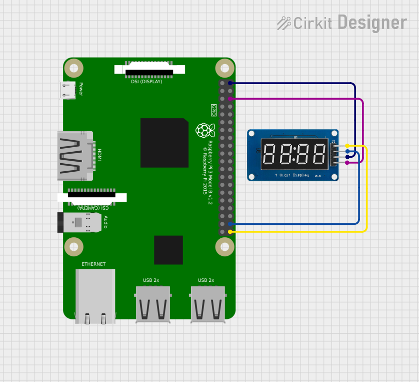
Q: Can I use the TM1637 with a Raspberry Pi?
A: Yes, the TM1637 can be used with a Raspberry Pi. However, you will need to use a library or write custom code to handle the two-wire communication.
Q: How do I display letters or custom characters?
A: The TM1637 supports custom segment control. Refer to the library documentation for functions that allow you to define custom segment patterns.
By following this documentation, you should be able to successfully integrate and use the TM1637 in your projects.