How to Use Rj45 Port: Examples, Pinouts, and Specs

 Design with Rj45 Port in Cirkit Designer
Introduction
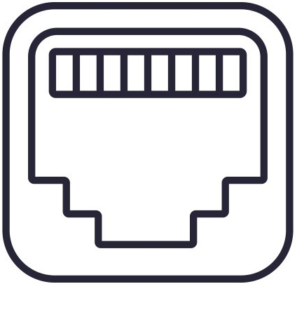
The RJ45 port is a standardized networking interface used for Ethernet connections. It is commonly found in networking devices such as routers, switches, and computers. The RJ45 port is essential for establishing wired network connections, enabling high-speed data transfer and reliable communication between devices.
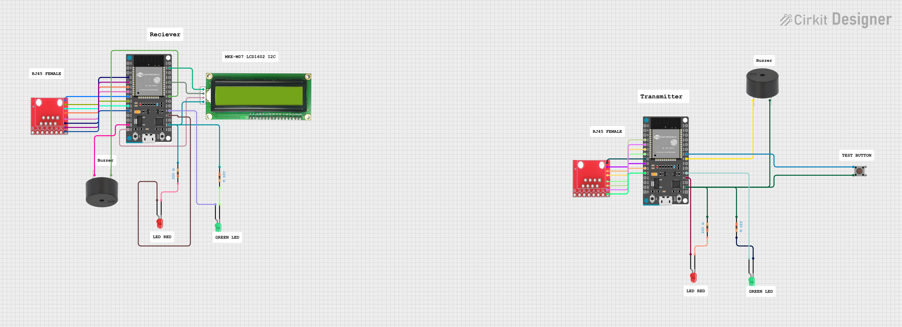
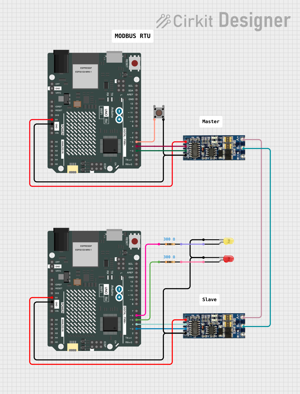
Explore Projects Built with Rj45 Port

 Open Project in Cirkit Designer
 Open Project in Cirkit Designer
 Open Project in Cirkit Designer
 Open Project in Cirkit Designer
Explore Projects Built with Rj45 Port

 Open Project in Cirkit Designer
 Open Project in Cirkit Designer
 Open Project in Cirkit Designer
 Open Project in Cirkit Designer
Technical Specifications
Key Technical Details
| Specification | Value |
|---|---|
| Connector Type | RJ45 |
| Number of Pins | 8 |
| Supported Standards | Ethernet (10/100/1000 Mbps) |
| Voltage Rating | 150V AC |
| Current Rating | 1.5A |
| Insulation Resistance | 500 MΩ min |
| Contact Resistance | 20 mΩ max |
| Operating Temperature | -40°C to +85°C |
Pin Configuration and Descriptions
| Pin Number | Signal Name | Description |
|---|---|---|
| 1 | TX+ | Transmit Data + |
| 2 | TX- | Transmit Data - |
| 3 | RX+ | Receive Data + |
| 4 | BI_D3+ | Bi-directional Data 3 + (Gigabit) |
| 5 | BI_D3- | Bi-directional Data 3 - (Gigabit) |
| 6 | RX- | Receive Data - |
| 7 | BI_D4+ | Bi-directional Data 4 + (Gigabit) |
| 8 | BI_D4- | Bi-directional Data 4 - (Gigabit) |
Usage Instructions
How to Use the RJ45 Port in a Circuit
Wiring the RJ45 Port:
- Use a Cat5e or Cat6 Ethernet cable for connecting devices.
- Ensure the cable is properly crimped with an RJ45 connector at both ends.
- Connect one end of the cable to the RJ45 port on your device (e.g., computer, router).
Connecting to an Arduino UNO:
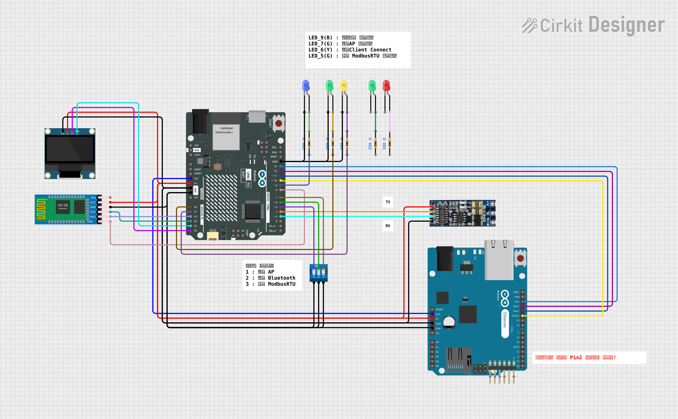
- While the RJ45 port itself cannot be directly connected to an Arduino UNO, you can use an Ethernet shield that includes an RJ45 port.
- Attach the Ethernet shield to the Arduino UNO.
- Connect the Ethernet cable to the RJ45 port on the Ethernet shield.
Important Considerations and Best Practices
- Cable Quality: Use high-quality Ethernet cables to ensure reliable connections and optimal data transfer rates.
- Proper Crimping: Ensure that the RJ45 connectors are properly crimped to avoid connection issues.
- Avoid Bending: Do not excessively bend or twist the Ethernet cable to prevent damage to the internal wires.
- Shielding: In environments with high electromagnetic interference, consider using shielded Ethernet cables (STP) to reduce noise.
Example Code for Arduino UNO with Ethernet Shield
#include <SPI.h>
#include <Ethernet.h>

// MAC address for the Ethernet shield
byte mac[] = { 0xDE, 0xAD, 0xBE, 0xEF, 0xFE, 0xED };

// IP address for the Arduino
IPAddress ip(192, 168, 1, 177);

// Initialize the Ethernet server library
// with the IP address and port you want to use
EthernetServer server(80);

void setup() {
  // Start the Ethernet connection and the server
  Ethernet.begin(mac, ip);
  server.begin();
  Serial.begin(9600);
  Serial.println("Server is at ");
  Serial.println(Ethernet.localIP());
}

void loop() {
  // Listen for incoming clients
  EthernetClient client = server.available();
  if (client) {
    Serial.println("New client");
    // An HTTP request ends with a blank line
    boolean currentLineIsBlank = true;
    while (client.connected()) {
      if (client.available()) {
        char c = client.read();
        Serial.write(c);
        // If you've gotten to the end of the line (received a newline
        // character) and the line is blank, the HTTP request has ended,
        // so you can send a reply
        if (c == '\n' && currentLineIsBlank) {
          // Send a standard HTTP response header
          client.println("HTTP/1.1 200 OK");
          client.println("Content-Type: text/html");
          client.println("Connection: close");
          client.println();
          // Display the HTML web page
          client.println("<!DOCTYPE HTML>");
          client.println("<html>");
          client.println("<h1>Hello, world!</h1>");
          client.println("</html>");
          break;
        }
        if (c == '\n') {
          // You're starting a new line
          currentLineIsBlank = true;
        } else if (c != '\r') {
          // You've gotten a character on the current line
          currentLineIsBlank = false;
        }
      }
    }
    // Give the web browser time to receive the data
    delay(1);
    // Close the connection
    client.stop();
    Serial.println("Client disconnected");
  }
}
Troubleshooting and FAQs
Common Issues Users Might Face
No Connection:
- Solution: Ensure that the Ethernet cable is properly connected and the RJ45 connectors are securely crimped. Verify that the Ethernet shield is correctly attached to the Arduino UNO.
Slow Data Transfer:
- Solution: Check the quality of the Ethernet cable. Use Cat6 cables for higher data transfer rates. Ensure that there are no excessive bends or twists in the cable.
Intermittent Connection:
- Solution: Inspect the Ethernet cable for any physical damage. Replace the cable if necessary. Ensure that the RJ45 connectors are free from dust and debris.
FAQs
Q1: Can I use an RJ45 port for non-Ethernet applications?
- A1: While the RJ45 port is primarily designed for Ethernet connections, it can be used for other applications that require similar pin configurations. However, it is recommended to use it for its intended purpose to ensure optimal performance.
Q2: What is the maximum cable length for an RJ45 connection?
- A2: The maximum recommended length for an Ethernet cable (Cat5e or Cat6) is 100 meters (328 feet) to maintain reliable data transfer rates.
Q3: Can I connect multiple devices to a single RJ45 port?
- A3: No, an RJ45 port is designed for a single connection. To connect multiple devices, use a network switch or router with multiple RJ45 ports.
Q4: How do I know if my Ethernet shield is working?
- A4: Check the status LEDs on the Ethernet shield. The link LED should be lit when a connection is established. You can also use the example code provided to test the connection.
By following this documentation, users can effectively utilize the RJ45 port for Ethernet connections, ensuring reliable and high-speed data transfer in their networking projects.