How to Use Socomec: Examples, Pinouts, and Specs

 Design with Socomec in Cirkit Designer
Introduction
Socomec is a renowned manufacturer of electrical equipment, specializing in energy management solutions, power monitoring, and safety devices for electrical installations. Their components are widely used in industrial, commercial, and residential applications to ensure efficient energy usage, reliable power distribution, and enhanced electrical safety.
Common applications and use cases include:
- Power monitoring and energy metering in industrial facilities.
- Load management and optimization in commercial buildings.
- Electrical safety and protection in critical installations.
- Integration with smart energy systems for real-time monitoring and control.
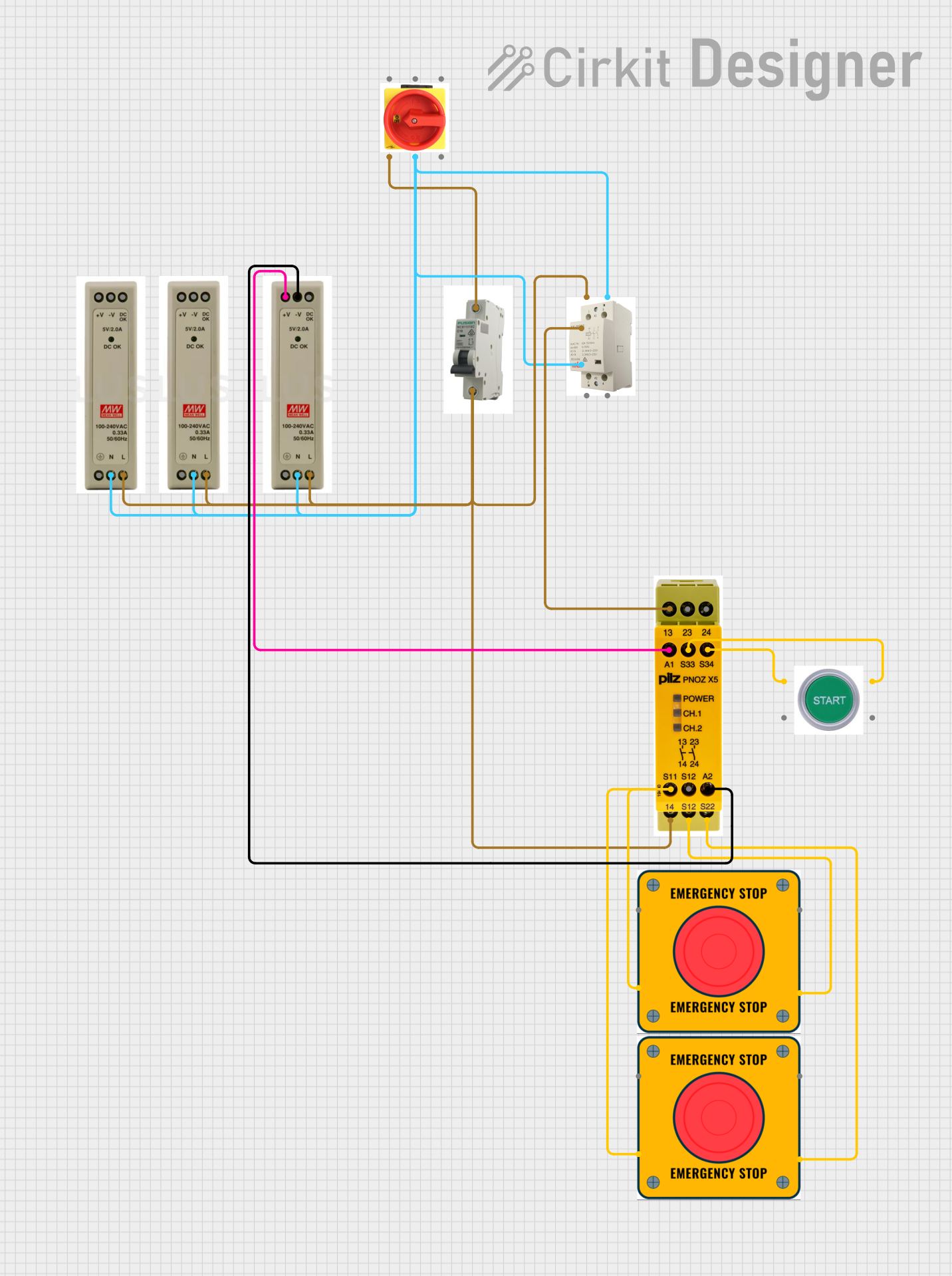
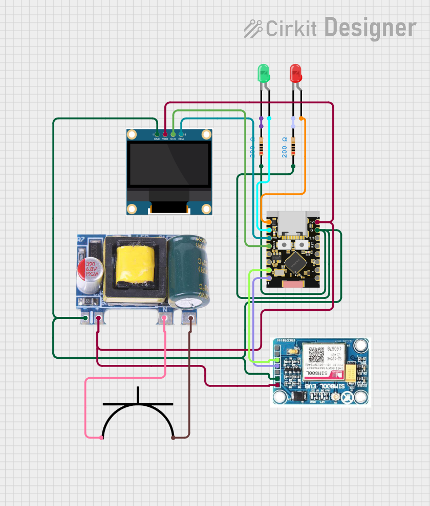
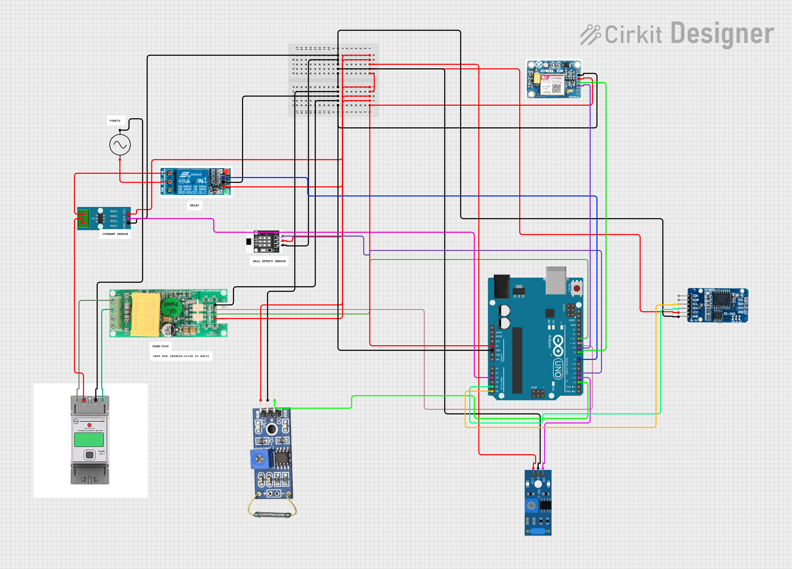
Explore Projects Built with Socomec

 Open Project in Cirkit Designer
 Open Project in Cirkit Designer
 Open Project in Cirkit Designer
 Open Project in Cirkit Designer
Explore Projects Built with Socomec

 Open Project in Cirkit Designer
 Open Project in Cirkit Designer
 Open Project in Cirkit Designer
 Open Project in Cirkit Designer
Technical Specifications
The technical specifications of Socomec components vary depending on the specific product line. Below is an example of a general-purpose Socomec energy meter:
Key Technical Details
- Model: Socomec DIRIS A40
- Voltage Range: 50-500V AC (phase-to-phase), 28-290V AC (phase-to-neutral)
- Current Range: 1A or 5A (via current transformers)
- Frequency: 50/60 Hz
- Accuracy: Class 0.5S (active energy)
- Power Supply: 110-400V AC or 120-350V DC
- Communication Protocols: Modbus RTU, Ethernet (optional)
- Operating Temperature: -10°C to +55°C
- Mounting: DIN rail or panel mount
Pin Configuration and Descriptions
Below is a typical pin configuration for a Socomec energy meter:
| Pin Number | Label | Description |
|---|---|---|
| 1, 2, 3 | L1, L2, L3 | Phase inputs for voltage measurement |
| 4 | N | Neutral input for voltage measurement |
| 5, 6, 7 | I1, I2, I3 | Current transformer inputs for phases 1, 2, and 3 |
| 8, 9 | RS485+ / RS485- | Modbus communication terminals |
| 10, 11 | AUX+ / AUX- | Auxiliary power supply input |
Usage Instructions
To use a Socomec energy meter in a circuit, follow these steps:
- Mounting: Install the device on a DIN rail or panel as per the manufacturer's instructions.
- Wiring:
- Connect the phase and neutral voltage inputs (L1, L2, L3, N) to the corresponding terminals.
- Use current transformers (CTs) to connect the current inputs (I1, I2, I3). Ensure the CTs are correctly oriented.
- If communication is required, connect the RS485 terminals to a Modbus network.
- Provide auxiliary power to the AUX+ and AUX- terminals.
- Configuration:
- Power on the device and configure the settings (e.g., CT ratio, communication parameters) using the front panel or software.
- Integration:
- If using with a monitoring system, ensure the Modbus address and baud rate match the system's configuration.
- For advanced setups, integrate the device with SCADA or energy management software.
Important Considerations and Best Practices
- Always follow the wiring diagram provided in the product manual.
- Ensure the current transformers are rated for the expected load and are properly calibrated.
- Use shielded cables for RS485 communication to minimize interference.
- Verify the device's firmware version and update if necessary for compatibility with your system.
- Avoid exposing the device to extreme temperatures or humidity.
Example: Connecting to an Arduino UNO
To read data from a Socomec energy meter using Modbus RTU, you can use an RS485-to-TTL converter and the Arduino Modbus library. Below is an example code snippet:
#include <ModbusMaster.h>

// Instantiate ModbusMaster object
ModbusMaster node;

void setup() {
  Serial.begin(9600); // Initialize serial communication
  node.begin(1, Serial); // Set Modbus ID to 1 and use Serial for communication

  // Initialize RS485 communication
  pinMode(2, OUTPUT); // Set pin 2 as DE/RE control for RS485
  digitalWrite(2, LOW); // Set RS485 to receive mode
}

void loop() {
  uint8_t result;
  uint16_t data;

  // Request voltage data from register 0x0000
  result = node.readInputRegisters(0x0000, 1);

  if (result == node.ku8MBSuccess) {
    data = node.getResponseBuffer(0); // Get the voltage value
    Serial.print("Voltage: ");
    Serial.println(data); // Print the voltage value
  } else {
    Serial.println("Failed to read data"); // Print error message
  }

  delay(1000); // Wait 1 second before the next request
}
Note: Replace 0x0000 with the actual register address for the desired parameter (e.g., voltage, current) as specified in the Socomec Modbus register map.
Troubleshooting and FAQs
Common Issues and Solutions
No Power to the Device:
- Check the auxiliary power supply connections (AUX+ and AUX-).
- Verify the voltage level of the power supply.
Incorrect Readings:
- Ensure the current transformers are properly connected and oriented.
- Verify the CT ratio and other configuration settings.
Communication Failure:
- Check the RS485 wiring and ensure the A/B lines are not swapped.
- Verify the Modbus address, baud rate, and parity settings.
- Use a termination resistor (120 ohms) if the RS485 network is long.
Device Overheating:
- Ensure adequate ventilation around the device.
- Avoid operating the device beyond its specified temperature range.
FAQs
Q: Can I use a Socomec energy meter with renewable energy systems?
A: Yes, Socomec energy meters are compatible with renewable energy systems and can monitor parameters such as solar generation and energy consumption.
Q: How do I update the firmware on a Socomec device?
A: Refer to the product manual for firmware update instructions. Typically, this involves connecting the device to a PC via a communication interface and using Socomec's software tools.
Q: What is the maximum cable length for RS485 communication?
A: The maximum recommended cable length for RS485 is 1200 meters, but this may vary depending on the baud rate and cable quality.
Q: Can I use multiple Socomec devices on the same Modbus network?
A: Yes, you can connect multiple devices by assigning unique Modbus addresses to each device.