How to Use IP5310: Examples, Pinouts, and Specs
Introduction
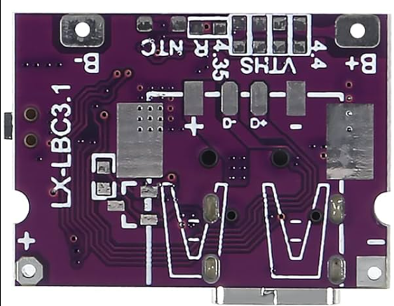
The IP5310 is a highly integrated power management integrated circuit (PMIC) designed for portable electronic devices. It combines a battery charger, power path management, and multiple output voltage regulators into a single compact package. This makes it an ideal choice for applications requiring efficient power distribution and battery management.
Explore Projects Built with IP5310


Explore Projects Built with IP5310
Common Applications and Use Cases
- Portable devices such as smartphones, tablets, and wearables
- Power banks and battery-powered gadgets
- IoT devices requiring efficient power management
- Embedded systems with rechargeable batteries
Technical Specifications
The IP5310 offers a range of features to simplify power management in portable devices. Below are its key technical specifications:
Key Technical Details
- Input Voltage Range: 4.5V to 5.5V
- Battery Charging Voltage: 4.2V (typical)
- Battery Charging Current: Up to 2A
- Output Voltage Regulators: Configurable for multiple voltage levels
- Quiescent Current: Low power consumption in standby mode
- Protection Features: Overvoltage, overcurrent, and thermal protection
- Package Type: QFN-24 (4mm x 4mm)
Pin Configuration and Descriptions
The IP5310 comes in a 24-pin QFN package. Below is the pin configuration and description:
| Pin Number | Pin Name | Description |
|---|---|---|
| 1 | VIN | Input power supply (4.5V to 5.5V) |
| 2 | BAT | Battery connection terminal |
| 3 | SYS | System power output |
| 4 | CHG_EN | Charger enable pin (active high) |
| 5 | STAT | Charging status indicator |
| 6 | ISET | Charging current setting |
| 7 | GND | Ground |
| 8 | VOUT1 | Output voltage regulator 1 |
| 9 | VOUT2 | Output voltage regulator 2 |
| 10 | EN1 | Enable pin for VOUT1 |
| 11 | EN2 | Enable pin for VOUT2 |
| 12 | NTC | Battery temperature monitoring input |
| 13-24 | NC | No connection (reserved for future use) |
Usage Instructions
The IP5310 is straightforward to use in a circuit. Below are the steps and best practices for integrating it into your design:
How to Use the IP5310 in a Circuit
- Power Input: Connect a 5V power source to the VIN pin. Ensure the input voltage is within the specified range (4.5V to 5.5V).
- Battery Connection: Connect the positive terminal of the battery to the BAT pin and the negative terminal to GND.
- System Power Output: Use the SYS pin to power your system. This pin provides regulated power from either the battery or the input source.
- Output Voltage Regulators: Configure VOUT1 and VOUT2 for your desired output voltages. Use the EN1 and EN2 pins to enable or disable these outputs.
- Charging Current: Set the charging current by connecting a resistor to the ISET pin. Refer to the datasheet for the resistor value corresponding to your desired current.
- Temperature Monitoring: Connect an NTC thermistor to the NTC pin for battery temperature monitoring. This ensures safe charging.
Important Considerations and Best Practices
- Thermal Management: Ensure proper heat dissipation by using a PCB with adequate thermal vias and copper planes.
- Protection Features: Take advantage of the built-in overvoltage, overcurrent, and thermal protection to safeguard your circuit.
- Battery Safety: Use a compatible lithium-ion or lithium-polymer battery with a built-in protection circuit.
- Decoupling Capacitors: Place decoupling capacitors close to the VIN, BAT, and SYS pins to reduce noise and improve stability.
Example: Using the IP5310 with an Arduino UNO
The IP5310 can be used to power an Arduino UNO and charge a battery simultaneously. Below is an example Arduino sketch to monitor the charging status:
// Example code to monitor the IP5310 charging status using Arduino UNO
// Connect the STAT pin of the IP5310 to Arduino digital pin 2

const int statPin = 2; // STAT pin connected to digital pin 2

void setup() {
  pinMode(statPin, INPUT); // Set STAT pin as input
  Serial.begin(9600);      // Initialize serial communication
}

void loop() {
  int chargingStatus = digitalRead(statPin); // Read the STAT pin

  if (chargingStatus == HIGH) {
    // STAT pin HIGH indicates charging is complete or not active
    Serial.println("Battery is fully charged or not charging.");
  } else {
    // STAT pin LOW indicates charging is in progress
    Serial.println("Battery is charging...");
  }

  delay(1000); // Wait for 1 second before checking again
}
Troubleshooting and FAQs
Common Issues and Solutions
Device Not Powering On
- Cause: Incorrect input voltage or loose connections.
- Solution: Verify that the input voltage is within the 4.5V to 5.5V range and check all connections.
Battery Not Charging
- Cause: Faulty battery or incorrect ISET resistor value.
- Solution: Check the battery's condition and ensure the ISET resistor is correctly calculated.
Overheating
- Cause: Insufficient thermal dissipation or excessive load.
- Solution: Improve PCB thermal design and reduce the load on the SYS pin.
Output Voltage Regulators Not Working
- Cause: EN1 or EN2 pins not enabled.
- Solution: Ensure the EN1 and EN2 pins are pulled high to enable the respective outputs.
FAQs
Can the IP5310 charge multiple batteries?
- No, the IP5310 is designed to charge a single lithium-ion or lithium-polymer battery.
What happens if the input voltage exceeds 5.5V?
- The IP5310 includes overvoltage protection, but it is recommended to keep the input voltage within the specified range to avoid damage.
Can I use the IP5310 without a battery?
- Yes, the SYS pin can provide power directly from the input source, but the battery management features will not be utilized.
This concludes the documentation for the IP5310. For further details, refer to the manufacturer's datasheet.