Cirkit Designer Logo
Cirkit Designer
Your all-in-one circuit design IDE
Home / 
Component Documentation

How to Use SparkFun Serial Basic Breakout - CH340G: Examples, Pinouts, and Specs

Image of SparkFun Serial Basic Breakout - CH340G
Cirkit Designer LogoDesign with SparkFun Serial Basic Breakout - CH340G in Cirkit Designer

Introduction

The SparkFun Serial Basic Breakout is a compact and user-friendly USB-to-serial adapter board that facilitates communication between a computer and a microcontroller or other serial devices. It employs the CH340G chip to provide a reliable USB-to-serial interface. This breakout is particularly useful for programming devices that do not have a USB interface, such as certain Arduino boards, or for adding a serial port to your computer.

Explore Projects Built with SparkFun Serial Basic Breakout - CH340G

Use Cirkit Designer to design, explore, and prototype these projects online. Some projects support real-time simulation. Click "Open Project" to start designing instantly!
ATMEGA328 Microcontroller Circuit with Serial Programming Interface
Image of breadboardArduino: A project utilizing SparkFun Serial Basic Breakout - CH340G in a practical application
This circuit features an ATMEGA328 microcontroller configured with a crystal oscillator for precise timing, and a pushbutton for reset functionality. An FTDI Programmer is connected for serial communication, allowing for programming and data exchange with the microcontroller.
Cirkit Designer LogoOpen Project in Cirkit Designer
ATMEGA328 Battery-Powered LED Blinker with FTDI Programming
Image of Homemade Arduino using ATmega328: A project utilizing SparkFun Serial Basic Breakout - CH340G in a practical application
This circuit is a basic microcontroller setup using an ATMEGA328, powered by a 5V battery, and includes an FTDI programmer for serial communication. It features a pushbutton for reset functionality and two LEDs controlled by the microcontroller, with one LED blinking at a 1-second interval as programmed.
Cirkit Designer LogoOpen Project in Cirkit Designer
ESP32 CAM-Based Impact Detection System with Serial Communication and LED Indicator
Image of esp32 cam: A project utilizing SparkFun Serial Basic Breakout - CH340G in a practical application
This circuit features an ESP32 CAM module interfaced with a SparkFun USB UART Breakout for serial communication, allowing the ESP32 to communicate with a computer or other USB host. A BC547 transistor is used to control an LED, with the base driven by one of the ESP32's GPIO pins through a resistor, and multiple piezo sensors are connected to the transistor's emitter, likely for sensing vibrations or impacts. The 5V Adapter provides power to the ESP32 and the LED, while the ground connections are shared among the components.
Cirkit Designer LogoOpen Project in Cirkit Designer
STM32F103C8T6 Bluetooth-Controlled Arcade Joystick Interface
Image of RC카 조이스틱: A project utilizing SparkFun Serial Basic Breakout - CH340G in a practical application
This circuit features an STM32F103C8T6 microcontroller interfaced with a Bluetooth HC-06 module for wireless communication and an Adafruit Arcade Joystick for user input. The microcontroller's pins B0 and B10 are connected to the TXD and RXD pins of the Bluetooth module, enabling serial communication, while pins B14 and B15 interface with the joystick's directional controls. The circuit is powered by a battery, with power distribution managed through the microcontroller's 3.3V pin and common ground connections.
Cirkit Designer LogoOpen Project in Cirkit Designer

Explore Projects Built with SparkFun Serial Basic Breakout - CH340G

Use Cirkit Designer to design, explore, and prototype these projects online. Some projects support real-time simulation. Click "Open Project" to start designing instantly!
Image of breadboardArduino: A project utilizing SparkFun Serial Basic Breakout - CH340G in a practical application
ATMEGA328 Microcontroller Circuit with Serial Programming Interface
This circuit features an ATMEGA328 microcontroller configured with a crystal oscillator for precise timing, and a pushbutton for reset functionality. An FTDI Programmer is connected for serial communication, allowing for programming and data exchange with the microcontroller.
Cirkit Designer LogoOpen Project in Cirkit Designer
Image of Homemade Arduino using ATmega328: A project utilizing SparkFun Serial Basic Breakout - CH340G in a practical application
ATMEGA328 Battery-Powered LED Blinker with FTDI Programming
This circuit is a basic microcontroller setup using an ATMEGA328, powered by a 5V battery, and includes an FTDI programmer for serial communication. It features a pushbutton for reset functionality and two LEDs controlled by the microcontroller, with one LED blinking at a 1-second interval as programmed.
Cirkit Designer LogoOpen Project in Cirkit Designer
Image of esp32 cam: A project utilizing SparkFun Serial Basic Breakout - CH340G in a practical application
ESP32 CAM-Based Impact Detection System with Serial Communication and LED Indicator
This circuit features an ESP32 CAM module interfaced with a SparkFun USB UART Breakout for serial communication, allowing the ESP32 to communicate with a computer or other USB host. A BC547 transistor is used to control an LED, with the base driven by one of the ESP32's GPIO pins through a resistor, and multiple piezo sensors are connected to the transistor's emitter, likely for sensing vibrations or impacts. The 5V Adapter provides power to the ESP32 and the LED, while the ground connections are shared among the components.
Cirkit Designer LogoOpen Project in Cirkit Designer
Image of RC카 조이스틱: A project utilizing SparkFun Serial Basic Breakout - CH340G in a practical application
STM32F103C8T6 Bluetooth-Controlled Arcade Joystick Interface
This circuit features an STM32F103C8T6 microcontroller interfaced with a Bluetooth HC-06 module for wireless communication and an Adafruit Arcade Joystick for user input. The microcontroller's pins B0 and B10 are connected to the TXD and RXD pins of the Bluetooth module, enabling serial communication, while pins B14 and B15 interface with the joystick's directional controls. The circuit is powered by a battery, with power distribution managed through the microcontroller's 3.3V pin and common ground connections.
Cirkit Designer LogoOpen Project in Cirkit Designer

Common Applications and Use Cases

  • Programming microcontrollers without onboard USB
  • Serial communication for debugging purposes
  • Bridging a USB connection to a serial device
  • Providing a serial interface for Raspberry Pi or similar boards

Technical Specifications

Key Technical Details

  • Voltage Levels: 3.3V and 5V compatible
  • Current Rating: 50mA
  • Interface: USB to Serial UART
  • Supported Baud Rates: Up to 115200 bps
  • Connectivity: Micro-USB

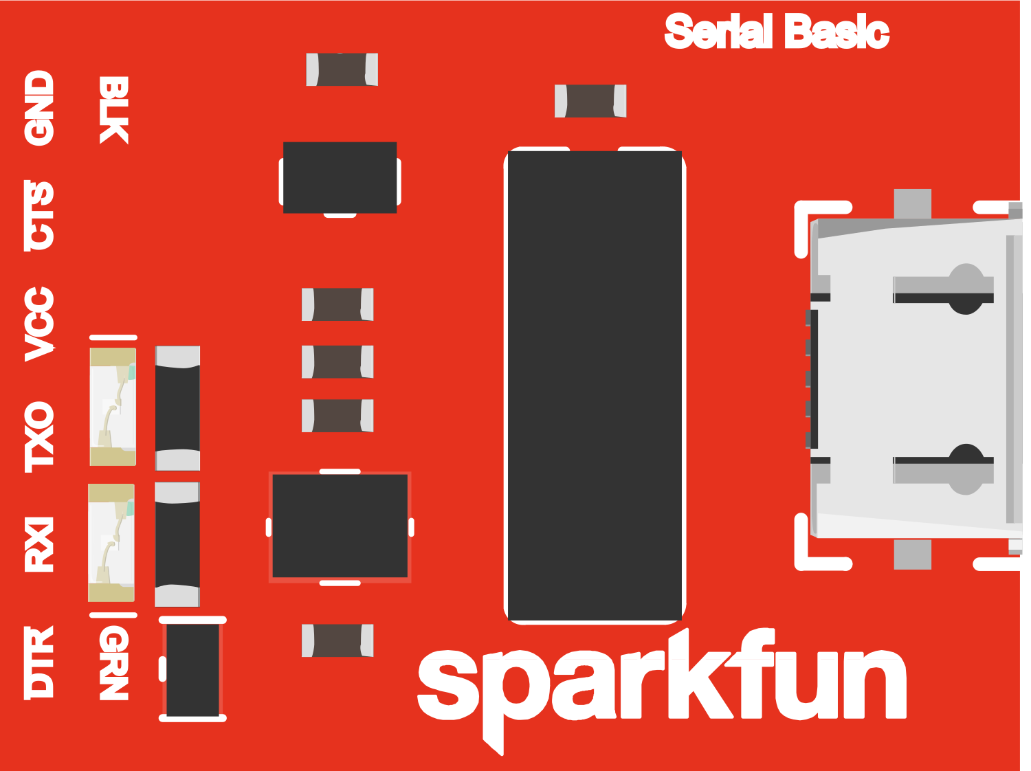
Pin Configuration and Descriptions

Pin Number Name Description
1 GND Ground connection
2 CTS Clear to Send, flow control signal input
3 VCC Power supply (3.3V or 5V)
4 TX-O Transmit Data, serial data output
5 RX-I Receive Data, serial data input
6 DTR Data Terminal Ready, used for resetting some microcontrollers during programming

Usage Instructions

How to Use the Component in a Circuit

  1. Connecting to a Microcontroller:

    • Connect the GND pin to the ground of the microcontroller.
    • Connect the TX-O pin to the RX pin on the microcontroller.
    • Connect the RX-I pin to the TX pin on the microcontroller.
    • Optionally, connect the DTR pin to the reset pin on the microcontroller if auto-reset is desired during programming.
  2. Powering the Breakout:

    • The VCC pin can be connected to either a 3.3V or 5V power supply, depending on the logic level required by the microcontroller.
  3. Connecting to a Computer:

    • Use a Micro-USB cable to connect the breakout board to a computer's USB port.
  4. Driver Installation:

    • Install the CH340G drivers on your computer if they are not already installed. Drivers are available on the SparkFun website.
  5. Serial Communication:

    • Use a serial terminal program to communicate with the microcontroller through the breakout board.

Important Considerations and Best Practices

  • Ensure that the logic levels (3.3V or 5V) match between the breakout board and the microcontroller to avoid damage.
  • Always disconnect the breakout board from the USB port before making or altering connections to the circuit.
  • Use quality USB cables to prevent connection issues.

Troubleshooting and FAQs

Common Issues Users Might Face

  • Driver Installation Problems: Ensure that the correct drivers for the CH340G chip are installed on your computer.
  • No Serial Communication: Check all connections, ensure that the correct COM port is selected, and verify that the baud rates match between the devices.
  • Device Not Recognized: Try a different USB cable or port, and ensure that the breakout board is not physically damaged.

Solutions and Tips for Troubleshooting

  • If the device is not recognized, reinstall the CH340G drivers and restart your computer.
  • For communication issues, double-check the wiring, especially the TX and RX connections, as they are often mistakenly reversed.
  • Ensure that the breakout board is not being powered at a voltage level that is incompatible with the connected microcontroller.

FAQs

Q: Do I need to install drivers for all operating systems? A: Drivers are typically required for Windows. Linux and macOS usually have built-in support for the CH340G chip.

Q: Can I use this breakout board to program an Arduino Pro Mini? A: Yes, the SparkFun Serial Basic Breakout can be used to program an Arduino Pro Mini and other similar boards that lack a USB interface.

Q: What is the purpose of the DTR pin? A: The DTR pin can be used to automatically reset certain microcontrollers during the programming process, allowing for a smoother workflow.

Q: Is the breakout board compatible with 5V systems? A: Yes, the breakout board can be configured to work with both 3.3V and 5V systems by connecting the VCC pin to the appropriate power supply.

Example Code for Arduino UNO

// This example demonstrates basic serial communication between the SparkFun Serial Basic Breakout
// and an Arduino UNO. The Arduino will echo any received characters back to the serial terminal.

void setup() {
  // Begin serial communication at a baud rate of 9600:
  Serial.begin(9600);
}

void loop() {
  // Check if data has been received:
  if (Serial.available() > 0) {
    // Read the incoming byte:
    char incomingByte = Serial.read();
    
    // Echo the byte back to the serial terminal:
    Serial.write(incomingByte);
  }
}

Remember to select the correct COM port and baud rate in your serial terminal program to match the settings in your Arduino sketch.