Cirkit Designer Logo
Cirkit Designer
Your all-in-one circuit design IDE
Home / 
Component Documentation

How to Use BC847PN: Examples, Pinouts, and Specs
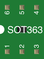

Image of BC847PN
Cirkit Designer LogoDesign with BC847PN in Cirkit Designer

Introduction

The BC847PN is a general-purpose NPN bipolar junction transistor (BJT) designed for switching and amplification in electronic circuits. It features low noise and high-speed operation, making it ideal for use in consumer electronics, signal processing, and small-signal amplification. Its compact SOT-363 package makes it suitable for space-constrained designs.

Explore Projects Built with BC847PN

Use Cirkit Designer to design, explore, and prototype these projects online. Some projects support real-time simulation. Click "Open Project" to start designing instantly!
Battery-Powered UPS with Step-Down Buck Converter and BMS
Image of Mini ups: A project utilizing BC847PN in a practical application
This circuit is a power management system that steps down a 240V AC input to a lower DC voltage using a buck converter, which then powers a 40W UPS. The UPS is controlled by a rocker switch and is backed up by a battery management system (BMS) connected to three 3.7V batteries in series, ensuring continuous power supply.
Cirkit Designer LogoOpen Project in Cirkit Designer
Satellite-Based Timing and Navigation System with SDR and Atomic Clock Synchronization
Image of GPS 시스템 측정 구성도_Confirm: A project utilizing BC847PN in a practical application
This circuit appears to be a complex system involving power supply management, GPS and timing synchronization, and data communication. It includes a SI-TEX G1 Satellite Compass for GPS data, an XHTF1021 Atomic Rubidium Clock for precise timing, and Ettus USRP B200 units for software-defined radio communication. Power is supplied through various SMPS units and distributed via terminal blocks and DC jacks. Data communication is facilitated by Beelink MINI S12 N95 computers, RS232 splitters, and a 1000BASE-T Media Converter for network connectivity. RF Directional Couplers are used to interface antennas with the USRP units, and the entire system is likely contained within cases for protection and organization.
Cirkit Designer LogoOpen Project in Cirkit Designer
Satellite Compass and Network-Integrated GPS Data Processing System
Image of GPS 시스템 측정 구성도_241016: A project utilizing BC847PN in a practical application
This circuit comprises a satellite compass, a mini PC, two GPS antennas, power supplies, a network switch, media converters, and an atomic rubidium clock. The satellite compass is powered by a triple output DC power supply and interfaces with an RS232 splitter for 1PPS signals. The mini PCs are connected to the USRP B200 devices via USB for data and power, and to media converters via Ethernet, which in turn connect to a network switch using fiber optic links. The antennas are connected to the USRP B200s through RF directional couplers, and the atomic clock provides a 1PPS input to the RS232 splitter.
Cirkit Designer LogoOpen Project in Cirkit Designer
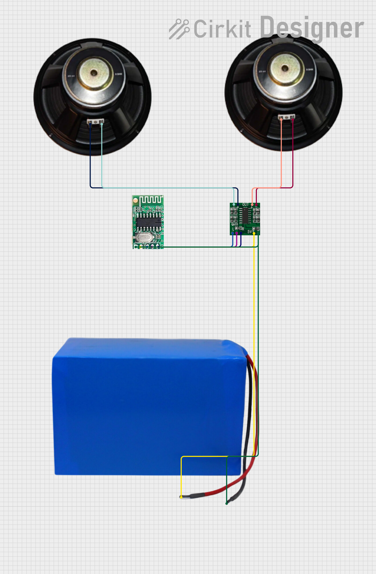
Battery-Powered Bluetooth Audio Amplifier with PAM8403
Image of trip: A project utilizing BC847PN in a practical application
This circuit is a Bluetooth audio amplifier system powered by a 38.5V battery. It uses a 5V Bluetooth audio receiver to receive audio signals, which are then amplified by a PAM8403 amplifier and output to two speakers for stereo sound.
Cirkit Designer LogoOpen Project in Cirkit Designer

Explore Projects Built with BC847PN

Use Cirkit Designer to design, explore, and prototype these projects online. Some projects support real-time simulation. Click "Open Project" to start designing instantly!
Image of Mini ups: A project utilizing BC847PN in a practical application
Battery-Powered UPS with Step-Down Buck Converter and BMS
This circuit is a power management system that steps down a 240V AC input to a lower DC voltage using a buck converter, which then powers a 40W UPS. The UPS is controlled by a rocker switch and is backed up by a battery management system (BMS) connected to three 3.7V batteries in series, ensuring continuous power supply.
Cirkit Designer LogoOpen Project in Cirkit Designer
Image of GPS 시스템 측정 구성도_Confirm: A project utilizing BC847PN in a practical application
Satellite-Based Timing and Navigation System with SDR and Atomic Clock Synchronization
This circuit appears to be a complex system involving power supply management, GPS and timing synchronization, and data communication. It includes a SI-TEX G1 Satellite Compass for GPS data, an XHTF1021 Atomic Rubidium Clock for precise timing, and Ettus USRP B200 units for software-defined radio communication. Power is supplied through various SMPS units and distributed via terminal blocks and DC jacks. Data communication is facilitated by Beelink MINI S12 N95 computers, RS232 splitters, and a 1000BASE-T Media Converter for network connectivity. RF Directional Couplers are used to interface antennas with the USRP units, and the entire system is likely contained within cases for protection and organization.
Cirkit Designer LogoOpen Project in Cirkit Designer
Image of GPS 시스템 측정 구성도_241016: A project utilizing BC847PN in a practical application
Satellite Compass and Network-Integrated GPS Data Processing System
This circuit comprises a satellite compass, a mini PC, two GPS antennas, power supplies, a network switch, media converters, and an atomic rubidium clock. The satellite compass is powered by a triple output DC power supply and interfaces with an RS232 splitter for 1PPS signals. The mini PCs are connected to the USRP B200 devices via USB for data and power, and to media converters via Ethernet, which in turn connect to a network switch using fiber optic links. The antennas are connected to the USRP B200s through RF directional couplers, and the atomic clock provides a 1PPS input to the RS232 splitter.
Cirkit Designer LogoOpen Project in Cirkit Designer
Image of trip: A project utilizing BC847PN in a practical application
Battery-Powered Bluetooth Audio Amplifier with PAM8403
This circuit is a Bluetooth audio amplifier system powered by a 38.5V battery. It uses a 5V Bluetooth audio receiver to receive audio signals, which are then amplified by a PAM8403 amplifier and output to two speakers for stereo sound.
Cirkit Designer LogoOpen Project in Cirkit Designer

Common Applications

  • Signal amplification in audio and RF circuits
  • Low-power switching applications
  • General-purpose amplification in consumer electronics
  • High-speed signal processing

Technical Specifications

Key Specifications

Parameter Value
Transistor Type NPN
Maximum Collector-Emitter Voltage (VCEO) 45 V
Maximum Collector-Base Voltage (VCBO) 50 V
Maximum Emitter-Base Voltage (VEBO) 6 V
Maximum Collector Current (IC) 500 mA
Power Dissipation (Ptot) 250 mW
DC Current Gain (hFE) 100 to 630
Transition Frequency (fT) 100 MHz
Noise Figure (NF) 2 dB (typical)
Package Type SOT-363

Pin Configuration

The BC847PN is a dual NPN transistor housed in a single SOT-363 package. The pinout is as follows:

Pin Number Pin Name Description
1 C1 Collector of Transistor 1
2 B1 Base of Transistor 1
3 E2 Emitter of Transistor 2
4 C2 Collector of Transistor 2
5 B2 Base of Transistor 2
6 E1 Emitter of Transistor 1

Usage Instructions

Using the BC847PN in a Circuit

The BC847PN is commonly used in circuits requiring two NPN transistors. Below are the steps to use it effectively:

  1. Determine the Operating Region: Ensure the transistor operates in the desired region (cutoff, active, or saturation) based on your application.
  2. Biasing: Properly bias the base of each transistor using resistors to control the current flow.
  3. Load Resistor: Connect a load resistor to the collector to limit the current and prevent damage.
  4. Voltage Ratings: Ensure the applied voltages do not exceed the maximum ratings (e.g., VCEO, VCBO, and VEBO).

Example Circuit with Arduino UNO

The BC847PN can be used with an Arduino UNO for switching or amplification. Below is an example of using one of the transistors in the BC847PN package to control an LED:

Circuit Description

  • The base of the transistor is connected to a digital pin of the Arduino through a current-limiting resistor.
  • The collector is connected to the positive terminal of the LED, and the emitter is connected to ground.
  • A resistor is placed in series with the LED to limit the current.

Arduino Code

// Define the pin connected to the transistor base
const int transistorBasePin = 9;

void setup() {
  // Set the transistor base pin as an output
  pinMode(transistorBasePin, OUTPUT);
}

void loop() {
  // Turn the LED on by driving the transistor base high
  digitalWrite(transistorBasePin, HIGH);
  delay(1000); // Keep the LED on for 1 second

  // Turn the LED off by driving the transistor base low
  digitalWrite(transistorBasePin, LOW);
  delay(1000); // Keep the LED off for 1 second
}

Important Considerations

  • Thermal Management: Ensure the power dissipation does not exceed 250 mW. Use proper heat sinking if necessary.
  • Current Limiting: Always use resistors to limit the base and collector currents to prevent damage.
  • Noise Sensitivity: For low-noise applications, ensure proper grounding and shielding to minimize interference.

Troubleshooting and FAQs

Common Issues and Solutions

  1. Transistor Not Switching Properly

    • Cause: Insufficient base current.
    • Solution: Check the base resistor value and ensure it provides enough current to saturate the transistor.
  2. Overheating

    • Cause: Exceeding the maximum power dissipation.
    • Solution: Reduce the collector current or improve thermal management.
  3. No Output Signal

    • Cause: Incorrect pin connections.
    • Solution: Verify the pinout and ensure proper connections to the base, collector, and emitter.
  4. Noise in Amplified Signal

    • Cause: Poor grounding or shielding.
    • Solution: Improve the grounding and use shielded cables for sensitive signals.

FAQs

Q: Can the BC847PN handle high-power applications?
A: No, the BC847PN is designed for low-power applications with a maximum collector current of 500 mA and power dissipation of 250 mW.

Q: Can I use both transistors in the BC847PN independently?
A: Yes, the BC847PN contains two independent NPN transistors that can be used separately in a circuit.

Q: What is the advantage of using the BC847PN in a compact package?
A: The SOT-363 package saves space on the PCB, making it ideal for compact and portable devices.

Q: Is the BC847PN suitable for high-frequency applications?
A: Yes, with a transition frequency (fT) of 100 MHz, it is suitable for high-speed signal processing and RF applications.