How to Use Micro:bit Breadboard adapter V1.6: Examples, Pinouts, and Specs
Introduction
The Micro:bit Breadboard Adapter V1.6 (Manufacturer Part ID: EF03404) by Elecfreaks is a compact and versatile adapter designed to connect the Micro:bit microcontroller to a standard breadboard. This adapter simplifies prototyping and circuit building by providing easy access to the Micro:bit's GPIO pins in a breadboard-friendly format. It is an essential tool for hobbyists, students, and professionals working on Micro:bit-based projects.
Explore Projects Built with Micro:bit Breadboard adapter V1.6

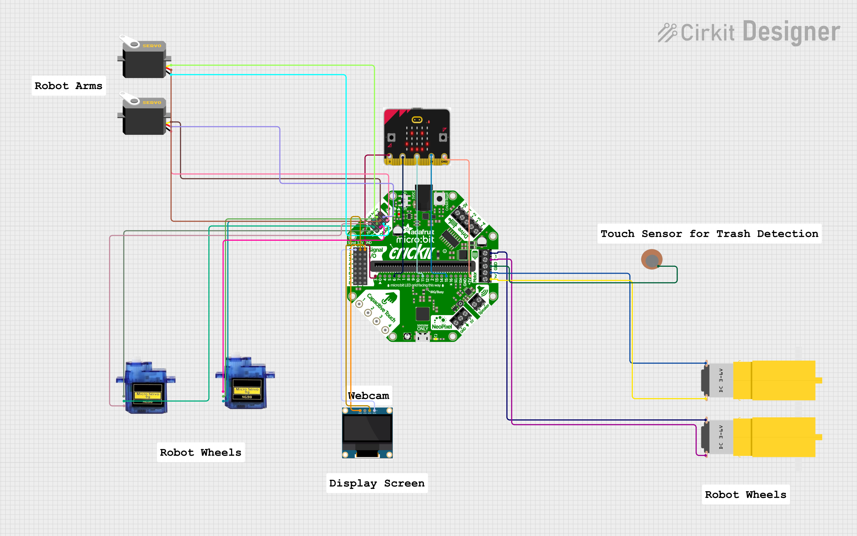

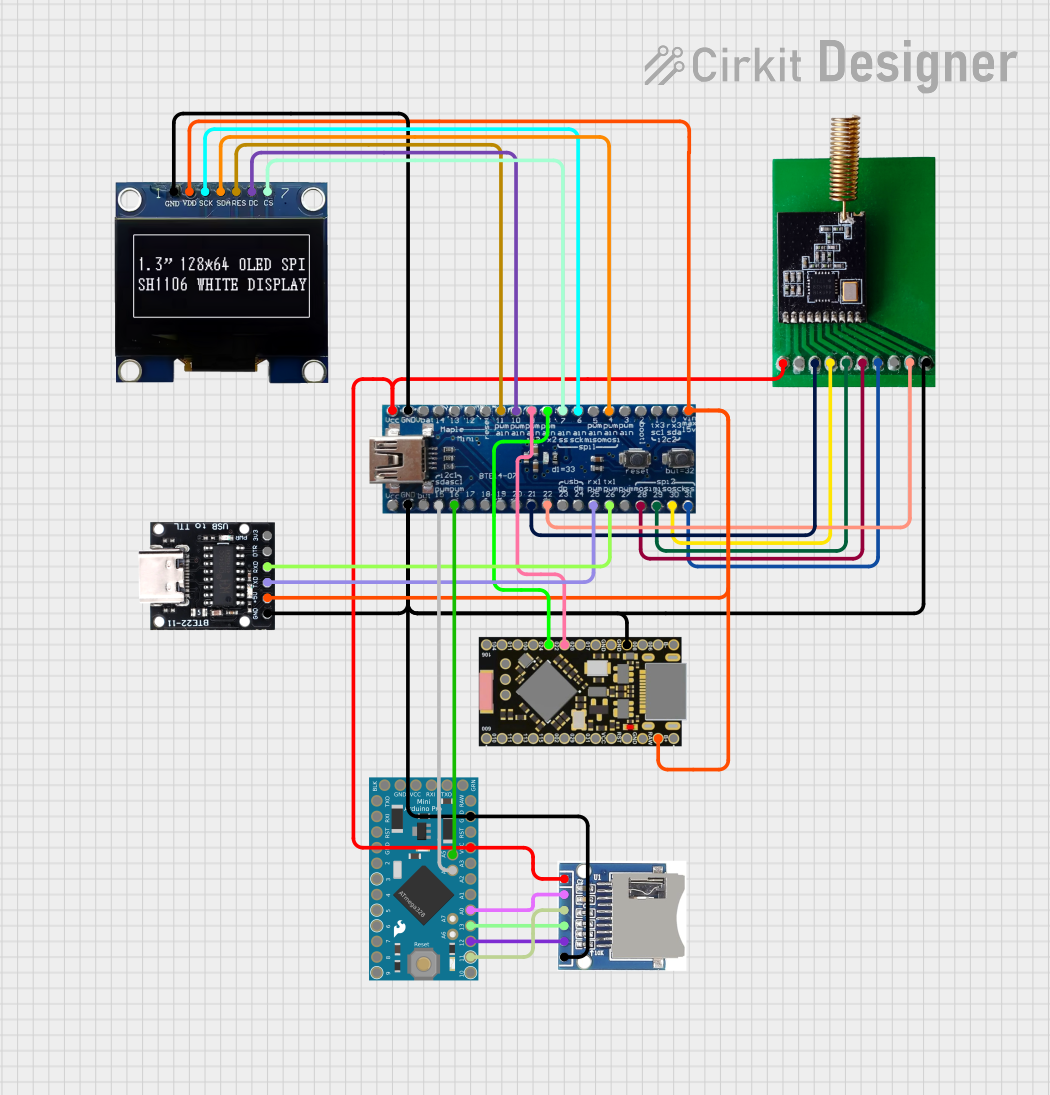
Explore Projects Built with Micro:bit Breadboard adapter V1.6
Common Applications and Use Cases
- Prototyping circuits with the Micro:bit microcontroller.
- Educational projects and STEM learning activities.
- Building and testing custom electronic circuits.
- Interfacing sensors, actuators, and other peripherals with the Micro:bit.
Technical Specifications
The following table outlines the key technical details of the Micro:bit Breadboard Adapter V1.6:
| Specification | Details |
|---|---|
| Manufacturer | Elecfreaks |
| Part ID | EF03404 |
| Compatibility | Micro:bit V1 and V2 |
| Breadboard Compatibility | Standard 830-point and 400-point breadboards |
| Dimensions | 58mm x 30mm x 12mm |
| Weight | 10g |
| Operating Voltage | 3.3V (provided by the Micro:bit) |
| Pin Output | Breakout of all Micro:bit GPIO pins to breadboard-friendly male headers |
| Material | PCB with gold-plated connectors |
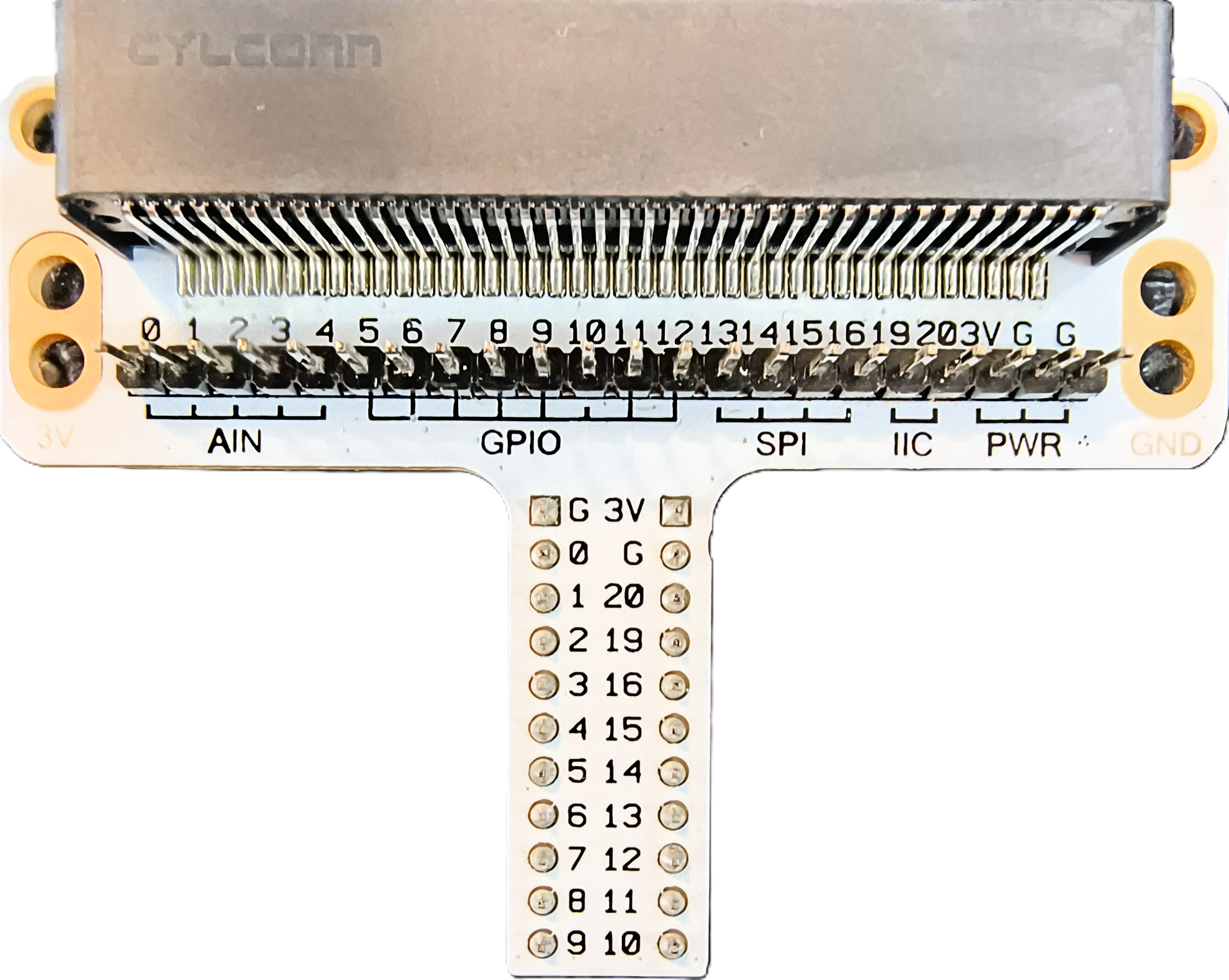
Pin Configuration and Descriptions
The Micro:bit Breadboard Adapter V1.6 breaks out the Micro:bit's GPIO pins into two rows of male headers, which can be easily inserted into a breadboard. The pin configuration is as follows:
| Pin Name | Description |
|---|---|
| 3V | 3.3V power output from the Micro:bit. Used to power external components. |
| GND | Ground connection. Common ground for the circuit. |
| P0-P20 | General-purpose input/output (GPIO) pins. Can be used for digital/analog I/O. |
| 5V | Optional 5V power output (if connected via USB to the Micro:bit). |
Usage Instructions
How to Use the Adapter in a Circuit
- Insert the Micro:bit: Align the Micro:bit's edge connector with the adapter's slot and gently insert it until it is securely seated.
- Connect to a Breadboard: Place the adapter's male header pins into the breadboard. Ensure the pins are aligned with the breadboard rows.
- Wire Your Circuit: Use jumper wires to connect components (e.g., LEDs, resistors, sensors) to the appropriate GPIO pins on the breadboard.
- Power the Circuit: Power the Micro:bit via USB or a battery pack. The adapter will provide 3.3V and GND to the breadboard.
Important Considerations and Best Practices
- Pin Voltage Levels: The GPIO pins operate at 3.3V. Avoid connecting components that require higher voltages directly to the pins.
- Current Limitations: The Micro:bit's GPIO pins have limited current-driving capability (approximately 5-10mA per pin). Use external transistors or drivers for high-current loads.
- Breadboard Placement: Ensure the adapter is firmly seated in the breadboard to avoid loose connections.
- Static Precautions: Handle the Micro:bit and adapter with care to prevent damage from static electricity.
Example: Connecting an LED to the Micro:bit
Below is an example of how to connect an LED to GPIO pin P0 using the adapter and control it with the Micro:bit:
Circuit Setup
- Connect the longer leg (anode) of the LED to P0 on the breadboard.
- Connect a 220-ohm resistor between the shorter leg (cathode) of the LED and GND.
- Power the Micro:bit via USB.
Micro:bit Code
Import the Micro:bit module
from microbit import *
Main loop
while True: pin0.write_digital(1) # Turn the LED on sleep(1000) # Wait for 1 second pin0.write_digital(0) # Turn the LED off sleep(1000) # Wait for 1 second
Troubleshooting and FAQs
Common Issues and Solutions
Micro:bit Not Powering On
- Ensure the Micro:bit is properly seated in the adapter.
- Check the USB or battery connection to the Micro:bit.
Loose Connections on the Breadboard
- Verify that the adapter's pins are fully inserted into the breadboard.
- Ensure jumper wires and components are securely connected.
Components Not Working
- Double-check the wiring and ensure components are connected to the correct GPIO pins.
- Verify that the components are compatible with the Micro:bit's 3.3V logic level.
LED Not Lighting Up
- Ensure the LED is connected with the correct polarity (anode to GPIO, cathode to GND).
- Check the resistor value; it should limit current appropriately (e.g., 220 ohms).
FAQs
Q: Can I use this adapter with other microcontrollers?
A: No, this adapter is specifically designed for the Micro:bit and is not compatible with other microcontrollers.
Q: Does the adapter provide additional power regulation?
A: No, the adapter relies on the Micro:bit's built-in power regulation. Ensure the Micro:bit is powered via USB or a battery pack.
Q: Can I use the adapter with a 5V breadboard power supply?
A: Yes, but ensure that the 5V supply is not directly connected to the Micro:bit's GPIO pins, as they operate at 3.3V.
Q: Is the adapter compatible with both Micro:bit V1 and V2?
A: Yes, the adapter is fully compatible with both versions of the Micro:bit.
By following this documentation, you can effectively use the Micro:bit Breadboard Adapter V1.6 to build and prototype your electronic projects with ease!