How to Use ANALOG INPUTS TO RS-485 : Examples, Pinouts, and Specs
Introduction
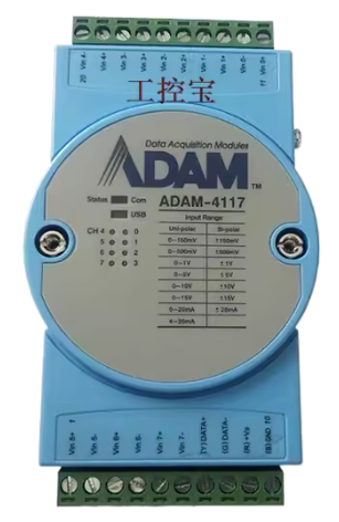
The ADAM-4117, manufactured by NI National Instrument, is a versatile analog-to-digital signal conversion module. It is designed to convert analog signals into a digital format suitable for transmission over RS-485 communication lines. This component is widely used in industrial environments for long-distance data acquisition and monitoring.
Explore Projects Built with ANALOG INPUTS TO RS-485


Explore Projects Built with ANALOG INPUTS TO RS-485
Common Applications and Use Cases
- Industrial automation and process control
- Remote data acquisition systems
- Environmental monitoring
- Factory equipment monitoring
- SCADA (Supervisory Control and Data Acquisition) systems
The ADAM-4117 is particularly valued for its ability to handle multiple analog input channels and transmit data reliably over long distances using the RS-485 protocol.
Technical Specifications
Key Technical Details
- Manufacturer: NI National Instrument
- Part ID: ADAM-4117
- Input Channels: 8 differential analog input channels
- Input Range: ±10V, ±5V, ±1V, ±500mV (software configurable)
- Resolution: 16-bit
- Communication Protocol: RS-485
- Baud Rate: 1,200 to 115,200 bps
- Power Supply: 10 to 30 VDC
- Isolation Voltage: 3,000 VDC
- Operating Temperature: -10°C to 70°C
- Accuracy: ±0.1% of full scale
Pin Configuration and Descriptions
The ADAM-4117 module features a terminal block for wiring connections. Below is the pin configuration:
| Pin Number | Pin Name | Description |
|---|---|---|
| 1 | AI0+ | Positive input for analog channel 0 |
| 2 | AI0- | Negative input for analog channel 0 |
| 3 | AI1+ | Positive input for analog channel 1 |
| 4 | AI1- | Negative input for analog channel 1 |
| 5 | AI2+ | Positive input for analog channel 2 |
| 6 | AI2- | Negative input for analog channel 2 |
| 7 | AI3+ | Positive input for analog channel 3 |
| 8 | AI3- | Negative input for analog channel 3 |
| 9 | AI4+ | Positive input for analog channel 4 |
| 10 | AI4- | Negative input for analog channel 4 |
| 11 | AI5+ | Positive input for analog channel 5 |
| 12 | AI5- | Negative input for analog channel 5 |
| 13 | AI6+ | Positive input for analog channel 6 |
| 14 | AI6- | Negative input for analog channel 6 |
| 15 | AI7+ | Positive input for analog channel 7 |
| 16 | AI7- | Negative input for analog channel 7 |
| 17 | GND | Ground |
| 18 | +V | Power supply input (10-30 VDC) |
| 19 | DATA+ | RS-485 data line (positive) |
| 20 | DATA- | RS-485 data line (negative) |
Usage Instructions
How to Use the Component in a Circuit
- Power Supply: Connect a DC power supply (10-30 VDC) to the
+VandGNDpins. - Analog Inputs: Wire the analog sensors or devices to the appropriate
AI+andAI-pins for each channel. - RS-485 Communication: Connect the
DATA+andDATA-pins to the RS-485 network. - Configuration: Use the provided software or commands to configure the input range, baud rate, and other parameters.
- Data Acquisition: Once configured, the module will continuously convert analog signals to digital data and transmit it over the RS-485 network.
Important Considerations and Best Practices
- Ensure proper grounding to avoid noise interference in analog signals.
- Use shielded cables for analog inputs to minimize electromagnetic interference (EMI).
- Match the baud rate and communication settings of the ADAM-4117 with the RS-485 master device.
- Terminate the RS-485 network with a 120-ohm resistor at both ends to prevent signal reflections.
- Avoid exceeding the input voltage range to prevent damage to the module.
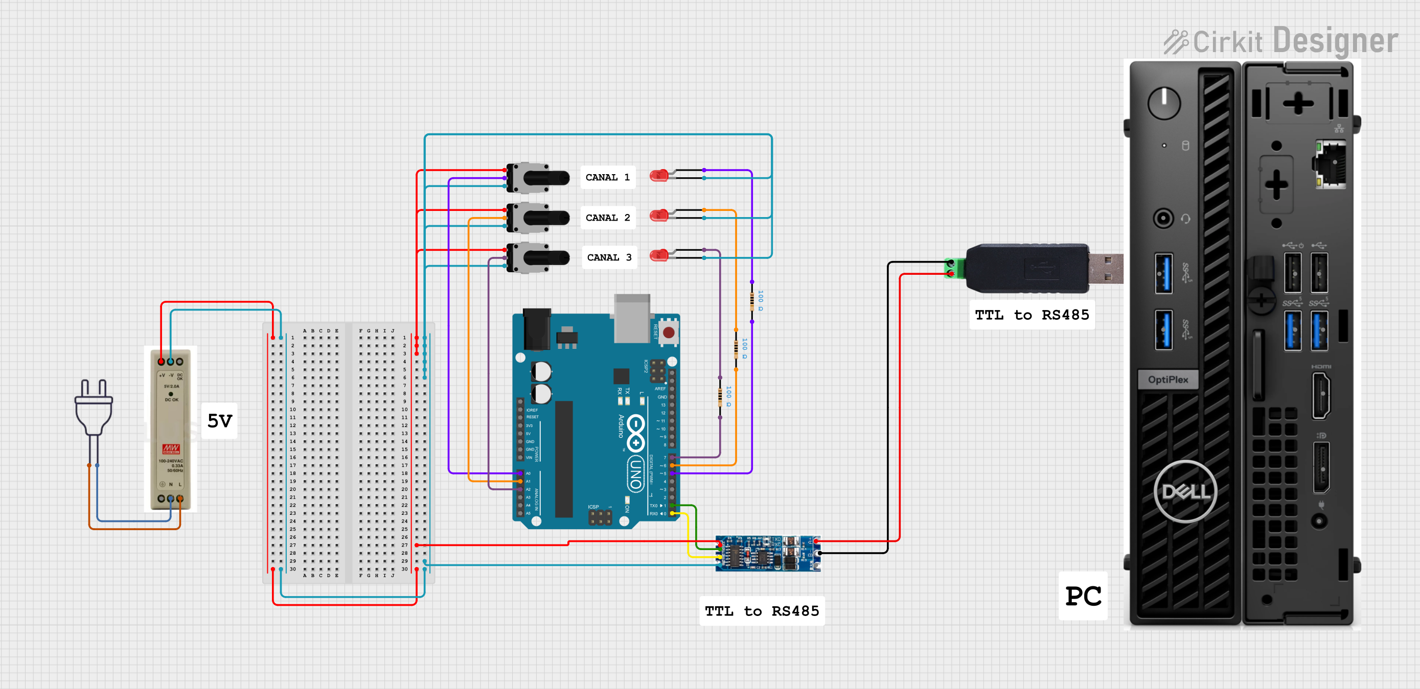
Example Code for Arduino UNO
The ADAM-4117 can be interfaced with an Arduino UNO using an RS-485 module. Below is an example code snippet:
#include <SoftwareSerial.h>

// Define RS-485 communication pins
#define RS485_RX 10  // Arduino pin connected to RS-485 module RX
#define RS485_TX 11  // Arduino pin connected to RS-485 module TX

// Create a SoftwareSerial object for RS-485 communication
SoftwareSerial rs485(RS485_RX, RS485_TX);

void setup() {
  // Initialize serial communication
  Serial.begin(9600);  // For debugging via Serial Monitor
  rs485.begin(9600);   // RS-485 communication baud rate

  // Send initialization command to ADAM-4117
  rs485.print("#01\r");  // Example command to read data from channel 1
  delay(100);
}

void loop() {
  // Check if data is available from ADAM-4117
  if (rs485.available()) {
    String data = "";
    while (rs485.available()) {
      char c = rs485.read();
      data += c;
    }
    // Print received data to Serial Monitor
    Serial.println("Received Data: " + data);
  }
}
Note: Replace
#01\rwith the appropriate command for your application. Refer to the ADAM-4117 command set for details.
Troubleshooting and FAQs
Common Issues and Solutions
No Data Received
- Cause: Incorrect baud rate or communication settings.
- Solution: Verify and match the baud rate and settings between the ADAM-4117 and the RS-485 master device.
Analog Input Readings Are Incorrect
- Cause: Input voltage exceeds the configured range or improper wiring.
- Solution: Check the input voltage range and ensure proper wiring of the analog inputs.
RS-485 Communication Fails
- Cause: Missing termination resistors or incorrect wiring.
- Solution: Add 120-ohm termination resistors at both ends of the RS-485 network and verify wiring.
Module Overheating
- Cause: Power supply voltage exceeds the specified range.
- Solution: Ensure the power supply voltage is within 10-30 VDC.
FAQs
Q: Can the ADAM-4117 handle single-ended inputs?
A: No, the ADAM-4117 is designed for differential input signals only.Q: What is the maximum cable length for RS-485 communication?
A: RS-485 supports cable lengths up to 1,200 meters (4,000 feet) at lower baud rates.Q: How many ADAM-4117 modules can be connected on the same RS-485 network?
A: Up to 32 devices can be connected on a single RS-485 network without repeaters.Q: Is the module compatible with Modbus protocol?
A: Yes, the ADAM-4117 supports Modbus/RTU communication.
By following this documentation, users can effectively integrate the ADAM-4117 into their industrial systems for reliable and accurate data acquisition.