How to Use BerryGPS-IMU-4: Examples, Pinouts, and Specs
Introduction
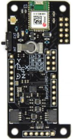
The BerryGPS-IMU-4 (Manufacturer Part ID: X001G63URN) is a compact and versatile GPS and IMU (Inertial Measurement Unit) module developed by OzzMaker. This module combines a high-performance GPS receiver with a 9-axis IMU, enabling precise location tracking and motion sensing. It is designed for applications such as robotics, drones, navigation systems, and other projects requiring accurate position, velocity, orientation, and acceleration data.
Explore Projects Built with BerryGPS-IMU-4

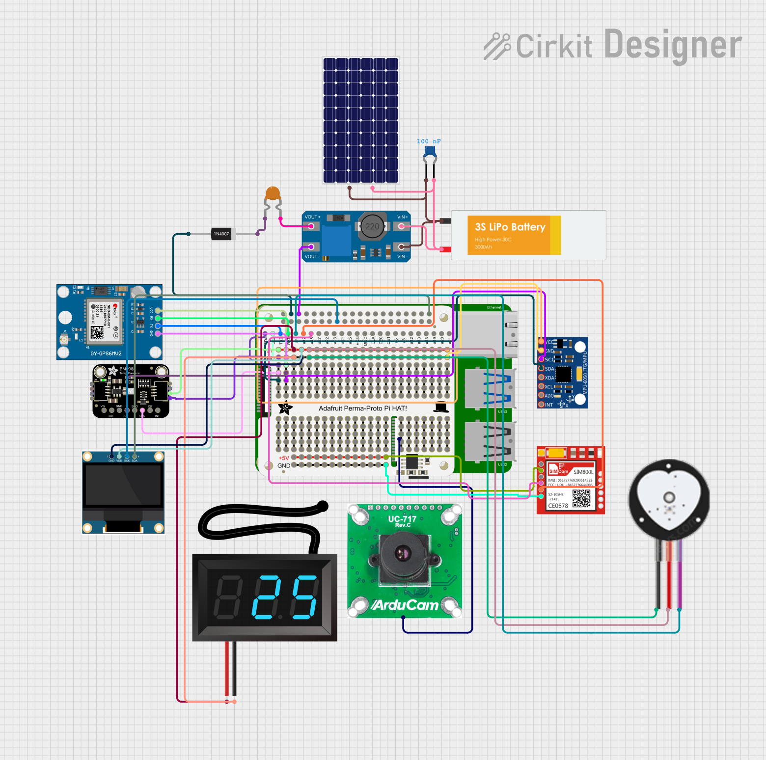
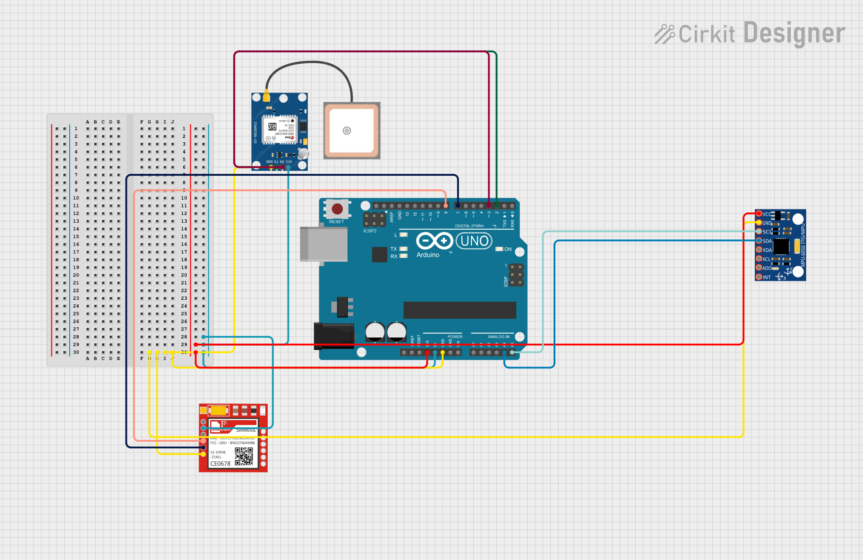
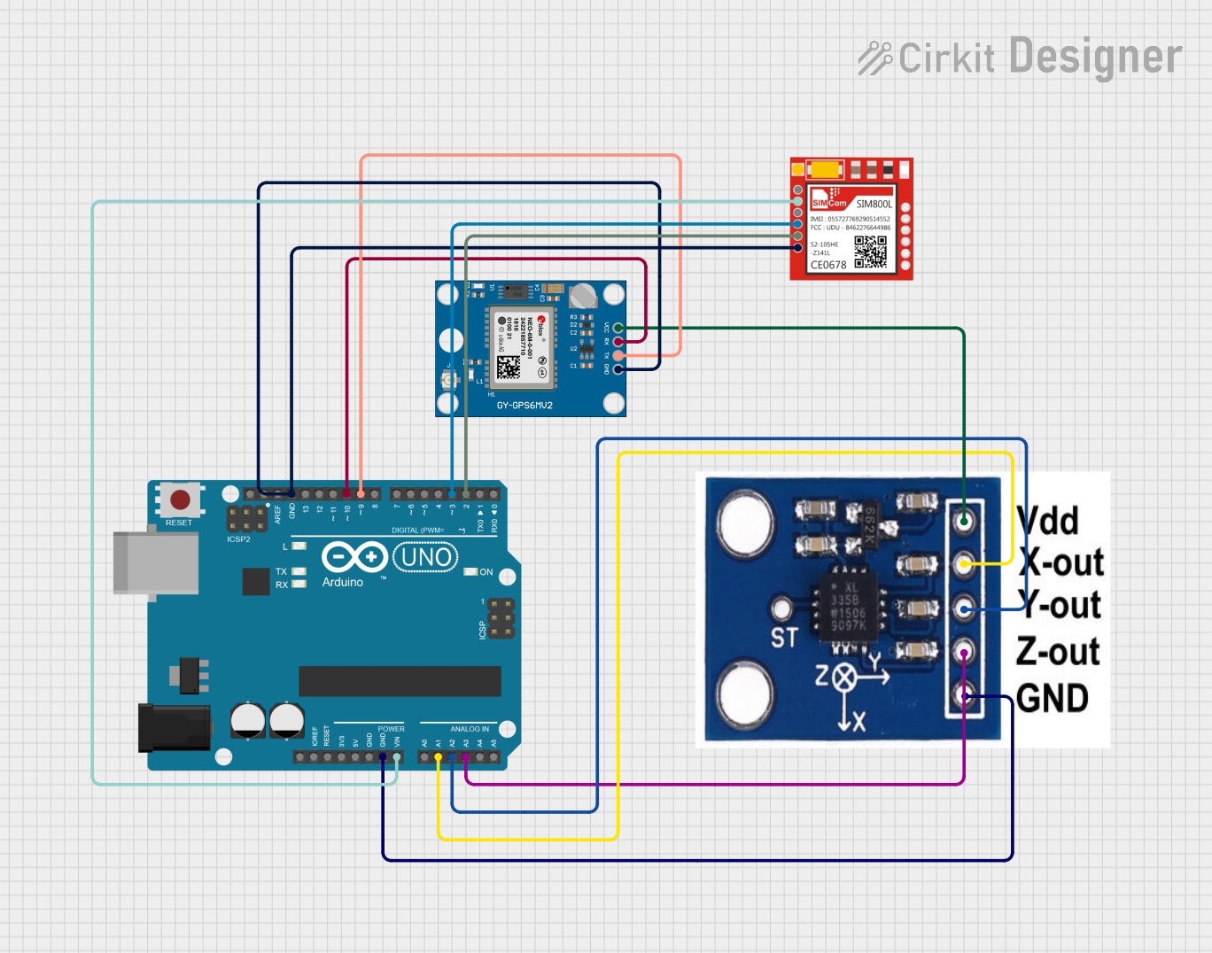
Explore Projects Built with BerryGPS-IMU-4
Common Applications
- Autonomous vehicles and drones
- Robotics and motion tracking
- Navigation systems
- Wearable devices
- IoT projects requiring geolocation and motion sensing
Technical Specifications
Key Technical Details
| Parameter | Specification |
|---|---|
| GPS Receiver | u-blox GPS module with high sensitivity |
| IMU Sensor | 9-axis IMU (accelerometer, gyroscope, magnetometer) |
| Communication Interface | I2C, UART, and GPIO |
| Operating Voltage | 3.3V to 5V |
| Power Consumption | ~30mA (typical) |
| Dimensions | 25mm x 25mm |
| Operating Temperature Range | -40°C to +85°C |
Pin Configuration and Descriptions
| Pin Name | Pin Number | Description |
|---|---|---|
| VIN | 1 | Power input (3.3V to 5V) |
| GND | 2 | Ground |
| SDA | 3 | I2C data line |
| SCL | 4 | I2C clock line |
| TX | 5 | UART transmit line |
| RX | 6 | UART receive line |
| PPS | 7 | Pulse-per-second output for GPS synchronization |
| INT | 8 | Interrupt pin for IMU |
Usage Instructions
How to Use the BerryGPS-IMU-4 in a Circuit
- Power the Module: Connect the VIN pin to a 3.3V or 5V power source and the GND pin to ground.
- Choose Communication Interface:
- For I2C communication, connect the SDA and SCL pins to the corresponding I2C pins on your microcontroller.
- For UART communication, connect the TX and RX pins to the UART pins on your microcontroller.
- Connect Additional Pins:
- Use the PPS pin for GPS synchronization if required.
- Connect the INT pin to your microcontroller if you need to handle IMU interrupts.
- Install Required Libraries: If using an Arduino, install the necessary libraries for GPS and IMU functionality (e.g., TinyGPS++ for GPS and Adafruit Sensor for IMU).
Important Considerations and Best Practices
- Ensure the module is placed in an open area for optimal GPS signal reception.
- Use pull-up resistors on the I2C lines (SDA and SCL) if your microcontroller does not have internal pull-ups.
- Avoid placing the module near sources of electromagnetic interference (EMI) to maintain accurate sensor readings.
- Calibrate the IMU sensors (accelerometer, gyroscope, and magnetometer) for improved accuracy.
Example Code for Arduino UNO
Below is an example code snippet to read GPS data using the BerryGPS-IMU-4 with an Arduino UNO:
#include <TinyGPS++.h>
#include <SoftwareSerial.h>

// Create a TinyGPS++ object to parse GPS data
TinyGPSPlus gps;

// Define RX and TX pins for SoftwareSerial
SoftwareSerial gpsSerial(4, 3); // RX = Pin 4, TX = Pin 3

void setup() {
  Serial.begin(9600);          // Initialize Serial Monitor
  gpsSerial.begin(9600);       // Initialize GPS module communication
  Serial.println("BerryGPS-IMU-4 GPS Test");
}

void loop() {
  // Read data from GPS module
  while (gpsSerial.available() > 0) {
    char c = gpsSerial.read();
    if (gps.encode(c)) {       // Parse GPS data
      if (gps.location.isUpdated()) {
        // Print latitude and longitude to Serial Monitor
        Serial.print("Latitude: ");
        Serial.print(gps.location.lat(), 6);
        Serial.print(", Longitude: ");
        Serial.println(gps.location.lng(), 6);
      }
    }
  }
}
Notes:
- Connect the GPS TX pin to Arduino RX (Pin 4) and GPS RX pin to Arduino TX (Pin 3).
- Install the TinyGPS++ library in the Arduino IDE via the Library Manager.
Troubleshooting and FAQs
Common Issues and Solutions
No GPS Signal Detected:
- Ensure the module is placed in an open area with a clear view of the sky.
- Check the power supply voltage and connections.
- Wait for a few minutes for the GPS to acquire a fix.
I2C Communication Not Working:
- Verify the SDA and SCL connections.
- Use pull-up resistors (4.7kΩ recommended) on the I2C lines if necessary.
- Check the I2C address of the module (default: 0x68 for IMU).
IMU Data is Inaccurate:
- Perform sensor calibration for the accelerometer, gyroscope, and magnetometer.
- Avoid placing the module near magnetic or metallic objects.
UART Communication Issues:
- Ensure the baud rate matches between the module and the microcontroller.
- Check the TX and RX pin connections.
FAQs
Q: Can the BerryGPS-IMU-4 be used with Raspberry Pi?
A: Yes, the module is compatible with Raspberry Pi. Use the I2C or UART interface and install the required libraries (e.g., RTIMULib for IMU and gpsd for GPS).
Q: How do I calibrate the IMU sensors?
A: Calibration can be performed using software tools or libraries like RTIMULib. Follow the library's documentation for detailed calibration steps.
Q: What is the typical GPS accuracy of the module?
A: The GPS module provides an accuracy of approximately 2.5 meters under optimal conditions.
Q: Can I use the module indoors?
A: While the IMU will function indoors, GPS signal reception may be limited or unavailable. Use the module in open areas for best results.