Cirkit Designer Logo
Cirkit Designer
Your all-in-one circuit design IDE
Home / 
Component Documentation

How to Use iKB-1: Examples, Pinouts, and Specs

Image of iKB-1
Cirkit Designer LogoDesign with iKB-1 in Cirkit Designer

Introduction

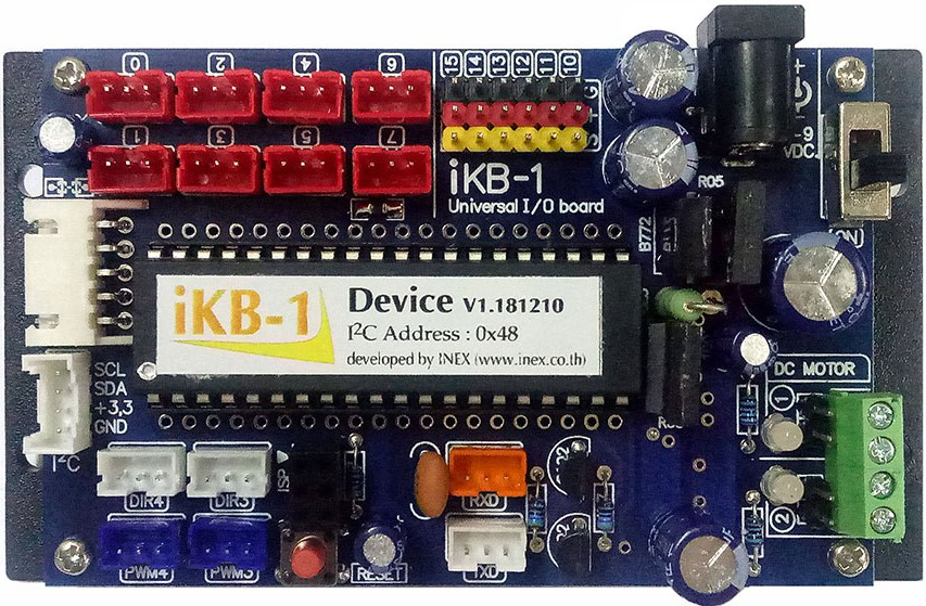
The iKB-1, manufactured by inex, is a versatile integrated circuit (IC) designed for use in a wide range of electronic applications. It provides functionalities such as signal processing, amplification, and control, all within a compact and efficient form factor. Its robust design and ease of integration make it suitable for both hobbyist projects and professional applications.

Explore Projects Built with iKB-1

Use Cirkit Designer to design, explore, and prototype these projects online. Some projects support real-time simulation. Click "Open Project" to start designing instantly!
MakerEdu Creator with Bluetooth, IR Sensors, LCD Display, and Push Button Interaction
Image of MKL Distance Measurement: A project utilizing iKB-1 in a practical application
This circuit features a MakerEdu Creator microcontroller board interfaced with two MKE-S11 IR Infrared Obstacle Avoidance Sensors, a MKE-M02 Push Button Tact Switch, a MKE-M15 Bluetooth module, and a MKE-M08 LCD2004 I2C display module. The push button is connected to a digital input for user interaction, while the IR sensors are likely used for detecting obstacles. The Bluetooth module enables wireless communication, and the LCD display provides a user interface for displaying information or statuses.
Cirkit Designer LogoOpen Project in Cirkit Designer
Battery-Powered Sumo Robot with IR Sensors and DC Motors
Image of MASSIVE SUMO AUTO BOARD: A project utilizing iKB-1 in a practical application
This circuit is designed for a robotic system, featuring a Massive Sumo Board as the central controller. It integrates multiple FS-80NK diffuse IR sensors and IR line sensors for obstacle detection and line following, respectively, and controls two GM25 DC motors via MD13s motor drivers for movement. Power is supplied by an 11.1V LiPo battery.
Cirkit Designer LogoOpen Project in Cirkit Designer
ESP32-Controlled Multi-Axis Actuator System with Orientation Sensing and Light Detection
Image of Auto_Level_Table: A project utilizing iKB-1 in a practical application
This circuit features an ESP32 S3 N32R8V microcontroller interfaced with multiple IBT-2 H-Bridge Motor Drivers to control several Linear Actuators, and it receives input from KY-018 LDR Photo Resistors and Pushbuttons. The ESP32 is powered by a 5V supply from an Adafruit MPM3610 5V Buck Converter, while the Linear Actuators and Motor Drivers are powered by a 12V 7Ah battery. Additionally, the ESP32 communicates with an Adafruit BNO085 9-DOF Orientation IMU Fusion Breakout for orientation sensing.
Cirkit Designer LogoOpen Project in Cirkit Designer
ESP32-Based Security System with RFID and Laser Intrusion Detection
Image of CPE doorlock system upgrade: A project utilizing iKB-1 in a practical application
This circuit is a security and access control system featuring motion detection, laser beam-break sensing, and RFID scanning, interfaced with a keypad and visual/audible indicators, powered by a solar-charged battery, and capable of controlling an electric lock via a relay.
Cirkit Designer LogoOpen Project in Cirkit Designer

Explore Projects Built with iKB-1

Use Cirkit Designer to design, explore, and prototype these projects online. Some projects support real-time simulation. Click "Open Project" to start designing instantly!
Image of MKL Distance Measurement: A project utilizing iKB-1 in a practical application
MakerEdu Creator with Bluetooth, IR Sensors, LCD Display, and Push Button Interaction
This circuit features a MakerEdu Creator microcontroller board interfaced with two MKE-S11 IR Infrared Obstacle Avoidance Sensors, a MKE-M02 Push Button Tact Switch, a MKE-M15 Bluetooth module, and a MKE-M08 LCD2004 I2C display module. The push button is connected to a digital input for user interaction, while the IR sensors are likely used for detecting obstacles. The Bluetooth module enables wireless communication, and the LCD display provides a user interface for displaying information or statuses.
Cirkit Designer LogoOpen Project in Cirkit Designer
Image of MASSIVE SUMO AUTO BOARD: A project utilizing iKB-1 in a practical application
Battery-Powered Sumo Robot with IR Sensors and DC Motors
This circuit is designed for a robotic system, featuring a Massive Sumo Board as the central controller. It integrates multiple FS-80NK diffuse IR sensors and IR line sensors for obstacle detection and line following, respectively, and controls two GM25 DC motors via MD13s motor drivers for movement. Power is supplied by an 11.1V LiPo battery.
Cirkit Designer LogoOpen Project in Cirkit Designer
Image of Auto_Level_Table: A project utilizing iKB-1 in a practical application
ESP32-Controlled Multi-Axis Actuator System with Orientation Sensing and Light Detection
This circuit features an ESP32 S3 N32R8V microcontroller interfaced with multiple IBT-2 H-Bridge Motor Drivers to control several Linear Actuators, and it receives input from KY-018 LDR Photo Resistors and Pushbuttons. The ESP32 is powered by a 5V supply from an Adafruit MPM3610 5V Buck Converter, while the Linear Actuators and Motor Drivers are powered by a 12V 7Ah battery. Additionally, the ESP32 communicates with an Adafruit BNO085 9-DOF Orientation IMU Fusion Breakout for orientation sensing.
Cirkit Designer LogoOpen Project in Cirkit Designer
Image of CPE doorlock system upgrade: A project utilizing iKB-1 in a practical application
ESP32-Based Security System with RFID and Laser Intrusion Detection
This circuit is a security and access control system featuring motion detection, laser beam-break sensing, and RFID scanning, interfaced with a keypad and visual/audible indicators, powered by a solar-charged battery, and capable of controlling an electric lock via a relay.
Cirkit Designer LogoOpen Project in Cirkit Designer

Common Applications and Use Cases

  • Signal amplification in audio and communication systems
  • Control systems for automation and robotics
  • Signal processing in sensor-based applications
  • General-purpose use in embedded systems and prototyping

Technical Specifications

Key Technical Details

Parameter Value
Manufacturer inex
Part ID iKB-1
Supply Voltage (Vcc) 3.3V to 5V
Operating Current 10 mA (typical)
Maximum Output Current 20 mA
Operating Temperature -40°C to +85°C
Package Type DIP-8 (Dual Inline Package)
Functionality Signal processing, amplification, control

Pin Configuration and Descriptions

Pin Number Pin Name Description
1 Vcc Power supply input (3.3V to 5V)
2 IN1 Input signal 1 for processing or amplification
3 IN2 Input signal 2 for processing or amplification
4 GND Ground connection
5 OUT1 Output signal 1
6 OUT2 Output signal 2
7 CTRL Control pin for enabling/disabling functionality
8 NC Not connected (leave unconnected or grounded)

Usage Instructions

How to Use the iKB-1 in a Circuit

  1. Power Supply: Connect the Vcc pin (Pin 1) to a stable power source within the range of 3.3V to 5V. Connect the GND pin (Pin 4) to the ground of the circuit.
  2. Input Signals: Feed the input signals to IN1 (Pin 2) and/or IN2 (Pin 3). Ensure the input signals are within the acceptable voltage range (0V to Vcc).
  3. Output Signals: The processed or amplified signals will be available at OUT1 (Pin 5) and OUT2 (Pin 6).
  4. Control Pin: Use the CTRL pin (Pin 7) to enable or disable the IC's functionality. Connect it to Vcc to enable or to GND to disable.
  5. Unused Pins: Leave the NC pin (Pin 8) unconnected or connect it to GND.

Important Considerations and Best Practices

  • Decoupling Capacitor: Place a 0.1 µF ceramic capacitor close to the Vcc pin to filter out noise and ensure stable operation.
  • Signal Integrity: Use shielded cables or proper PCB layout techniques to minimize noise in input and output signals.
  • Thermal Management: Ensure adequate ventilation or heat dissipation if the IC operates near its maximum current rating.
  • Avoid Overloading: Do not exceed the maximum output current of 20 mA to prevent damage to the IC.

Example: Using iKB-1 with Arduino UNO

The iKB-1 can be easily interfaced with an Arduino UNO for signal processing or control applications. Below is an example of how to use the iKB-1 to amplify an analog signal and read it using the Arduino.

// Example: Using iKB-1 with Arduino UNO
// This code reads an amplified signal from the iKB-1 and prints the value to Serial Monitor.

const int inputPin = A0;  // Connect OUT1 (Pin 5 of iKB-1) to Arduino A0
const int ctrlPin = 7;    // Connect CTRL (Pin 7 of iKB-1) to Arduino Digital Pin 7

void setup() {
  pinMode(ctrlPin, OUTPUT);  // Set CTRL pin as output
  digitalWrite(ctrlPin, HIGH);  // Enable the iKB-1 by setting CTRL pin HIGH
  Serial.begin(9600);  // Initialize Serial communication at 9600 baud
}

void loop() {
  int signalValue = analogRead(inputPin);  // Read the amplified signal
  Serial.print("Signal Value: ");
  Serial.println(signalValue);  // Print the signal value to Serial Monitor
  delay(500);  // Wait for 500 ms before the next reading
}

Troubleshooting and FAQs

Common Issues and Solutions

  1. No Output Signal:

    • Ensure the CTRL pin (Pin 7) is connected to Vcc to enable the IC.
    • Verify that the input signals are within the acceptable voltage range.
  2. Distorted Output Signal:

    • Check for noise in the power supply and add a decoupling capacitor if necessary.
    • Ensure the input signals are not exceeding the IC's input voltage limits.
  3. Overheating:

    • Verify that the output current does not exceed 20 mA.
    • Ensure proper ventilation or heat dissipation.
  4. Arduino Not Reading Signal:

    • Confirm that the OUT1 or OUT2 pin is properly connected to the Arduino's analog input pin.
    • Check the wiring and ensure there are no loose connections.

FAQs

Q: Can the iKB-1 operate at 12V?
A: No, the iKB-1 is designed to operate within a supply voltage range of 3.3V to 5V. Exceeding this range may damage the IC.

Q: Can I use both OUT1 and OUT2 simultaneously?
A: Yes, both output pins can be used simultaneously for different signals, provided the total output current does not exceed 20 mA.

Q: What happens if the CTRL pin is left floating?
A: Leaving the CTRL pin floating may result in unpredictable behavior. It is recommended to connect it to either Vcc (enable) or GND (disable).

Q: Is the iKB-1 suitable for audio applications?
A: Yes, the iKB-1 can be used for audio signal amplification, provided the input and output signals are within the specified voltage and current limits.