Cirkit Designer Logo
Cirkit Designer
Your all-in-one circuit design IDE
Home / 
Component Documentation

How to Use Power Mosfet Module: Examples, Pinouts, and Specs

Image of Power Mosfet Module
Cirkit Designer LogoDesign with Power Mosfet Module in Cirkit Designer

Introduction

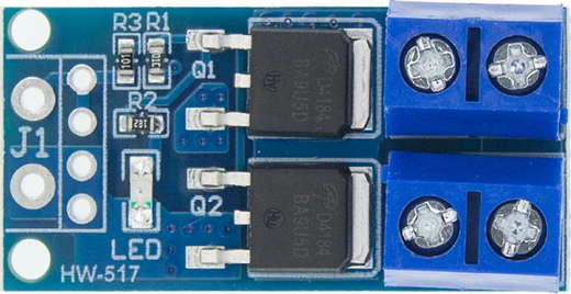
A Power MOSFET Module is a critical component in the realm of power electronics, serving as a fundamental building block for high-power and high-efficiency applications. This module is essentially a compact and integrated array of MOSFETs (Metal-Oxide-Semiconductor Field-Effect Transistors), which are designed to handle significant power levels while providing the ease of control that comes with a field-effect transistor. Common applications include motor drives, power inverters, power supplies, and any circuit requiring efficient switching and power control.

Explore Projects Built with Power Mosfet Module

Use Cirkit Designer to design, explore, and prototype these projects online. Some projects support real-time simulation. Click "Open Project" to start designing instantly!
DC-DC Converter and Relay Module Power Distribution System
Image of relay: A project utilizing Power Mosfet Module in a practical application
This circuit consists of a DC-DC converter powering a 6-channel power module, which in turn supplies 5V to a 2-relay module. The power module distributes the converted voltage to the relay module, enabling it to control external devices.
Cirkit Designer LogoOpen Project in Cirkit Designer
Battery-Powered Boost Converter with USB Type-C and BMS
Image of Weird Case: A project utilizing Power Mosfet Module in a practical application
This circuit is a power management and conversion system that includes a boost converter, battery management system (BMS), and various MOSFETs and passive components. It is designed to regulate and boost the voltage from a 2000mAh battery, providing stable power output through a USB Type C interface. The circuit also includes protection and switching mechanisms to ensure safe and efficient power delivery.
Cirkit Designer LogoOpen Project in Cirkit Designer
ESP32C3 and SIM800L Powered Smart Energy Monitor with OLED Display and Wi-Fi Connectivity
Image of SERVER: A project utilizing Power Mosfet Module in a practical application
This circuit is a power monitoring system that uses an ESP32C3 microcontroller to collect power usage data from slave devices via WiFi and SMS. The collected data is displayed on a 0.96" OLED screen, and the system is powered by an AC-DC converter module. Additionally, the circuit includes a SIM800L GSM module for SMS communication and LEDs for status indication.
Cirkit Designer LogoOpen Project in Cirkit Designer
Arduino Mega 2560 Based Security System with Fingerprint Authentication and SMS Alerts
Image of Door security system: A project utilizing Power Mosfet Module in a practical application
This circuit features an Arduino Mega 2560 microcontroller interfaced with a SIM800L GSM module, two fingerprint scanners, an I2C LCD display, an IR sensor, and a piezo buzzer. Power management is handled by a PowerBoost 1000 Basic Pad USB, a TP4056 charging module, and a Li-ion 18650 battery, with an option to use a Mini AC-DC 110V-230V to 5V 700mA module for direct power supply. The primary functionality appears to be a security system with GSM communication capabilities, biometric access control, and visual/audible feedback.
Cirkit Designer LogoOpen Project in Cirkit Designer

Explore Projects Built with Power Mosfet Module

Use Cirkit Designer to design, explore, and prototype these projects online. Some projects support real-time simulation. Click "Open Project" to start designing instantly!
Image of relay: A project utilizing Power Mosfet Module in a practical application
DC-DC Converter and Relay Module Power Distribution System
This circuit consists of a DC-DC converter powering a 6-channel power module, which in turn supplies 5V to a 2-relay module. The power module distributes the converted voltage to the relay module, enabling it to control external devices.
Cirkit Designer LogoOpen Project in Cirkit Designer
Image of Weird Case: A project utilizing Power Mosfet Module in a practical application
Battery-Powered Boost Converter with USB Type-C and BMS
This circuit is a power management and conversion system that includes a boost converter, battery management system (BMS), and various MOSFETs and passive components. It is designed to regulate and boost the voltage from a 2000mAh battery, providing stable power output through a USB Type C interface. The circuit also includes protection and switching mechanisms to ensure safe and efficient power delivery.
Cirkit Designer LogoOpen Project in Cirkit Designer
Image of SERVER: A project utilizing Power Mosfet Module in a practical application
ESP32C3 and SIM800L Powered Smart Energy Monitor with OLED Display and Wi-Fi Connectivity
This circuit is a power monitoring system that uses an ESP32C3 microcontroller to collect power usage data from slave devices via WiFi and SMS. The collected data is displayed on a 0.96" OLED screen, and the system is powered by an AC-DC converter module. Additionally, the circuit includes a SIM800L GSM module for SMS communication and LEDs for status indication.
Cirkit Designer LogoOpen Project in Cirkit Designer
Image of Door security system: A project utilizing Power Mosfet Module in a practical application
Arduino Mega 2560 Based Security System with Fingerprint Authentication and SMS Alerts
This circuit features an Arduino Mega 2560 microcontroller interfaced with a SIM800L GSM module, two fingerprint scanners, an I2C LCD display, an IR sensor, and a piezo buzzer. Power management is handled by a PowerBoost 1000 Basic Pad USB, a TP4056 charging module, and a Li-ion 18650 battery, with an option to use a Mini AC-DC 110V-230V to 5V 700mA module for direct power supply. The primary functionality appears to be a security system with GSM communication capabilities, biometric access control, and visual/audible feedback.
Cirkit Designer LogoOpen Project in Cirkit Designer

Technical Specifications

General Characteristics

  • Type: N-Channel or P-Channel (Specify as per the model)
  • Maximum Drain-Source Voltage (Vds): XX V
  • Maximum Continuous Drain Current (Id): XX A
  • Maximum Power Dissipation (Pd): XX W
  • Operating Temperature Range: -XX to +XX °C

Pin Configuration and Descriptions

Pin Number Name Description
1 Vgs Gate-Source Voltage Input
2 Vds Drain-Source Voltage Output
3 Id Drain Current Output
4 GND Ground Reference

Note: The pin configuration may vary depending on the specific model of the Power MOSFET Module. Always refer to the manufacturer's datasheet for exact details.

Usage Instructions

Integration into a Circuit

  1. Gate Drive: Apply a voltage to the gate (Vgs) to turn the MOSFET on. Ensure that this voltage does not exceed the maximum Vgs rating.
  2. Load Connection: Connect the load to the drain (Vds) and source terminals, ensuring that the current through the load does not exceed the maximum Id rating.
  3. Heat Management: Use appropriate heat sinks to manage the thermal dissipation, especially in high-power applications.

Best Practices

  • Always include a gate resistor to limit the inrush current to the gate and to dampen oscillations.
  • Use a flyback diode when switching inductive loads to prevent voltage spikes.
  • Ensure proper PCB layout to minimize stray inductance and capacitance for high-frequency applications.

Troubleshooting and FAQs

Common Issues

  • Overheating: If the module is overheating, check for overcurrent conditions, insufficient heat sinking, or inadequate airflow.
  • Unexpected Switching: Noise in the circuit or improper gate drive can cause unintended switching. Ensure proper gate drive design and circuit layout.

FAQs

Q: Can I use the Power MOSFET Module for AC applications? A: Yes, but you will need to ensure that the module is rated for AC operation and that you have the appropriate circuitry to handle AC signals.

Q: How do I choose the right heat sink for my application? A: Calculate the power dissipation and consult the heat sink manufacturer's datasheets to select a heat sink with the appropriate thermal resistance.

Example Code for Arduino UNO

// Example code to control a Power MOSFET Module with an Arduino UNO

const int mosfetGatePin = 3; // Connect to the gate of the MOSFET Module

void setup() {
  pinMode(mosfetGatePin, OUTPUT);
}

void loop() {
  digitalWrite(mosfetGatePin, HIGH); // Turn on the MOSFET
  delay(1000);                       // Wait for 1 second
  digitalWrite(mosfetGatePin, LOW);  // Turn off the MOSFET
  delay(1000);                       // Wait for 1 second
}

Note: The above code is a simple example of how to switch a Power MOSFET Module on and off with an Arduino UNO. Always ensure that the gate voltage levels are compatible with the Arduino's output.

This documentation provides a foundational understanding of the Power MOSFET Module and its use in electronic circuits. For more detailed information, always refer to the specific datasheet of the module you are using.