How to Use Zero-Cross Detector: Examples, Pinouts, and Specs
Introduction
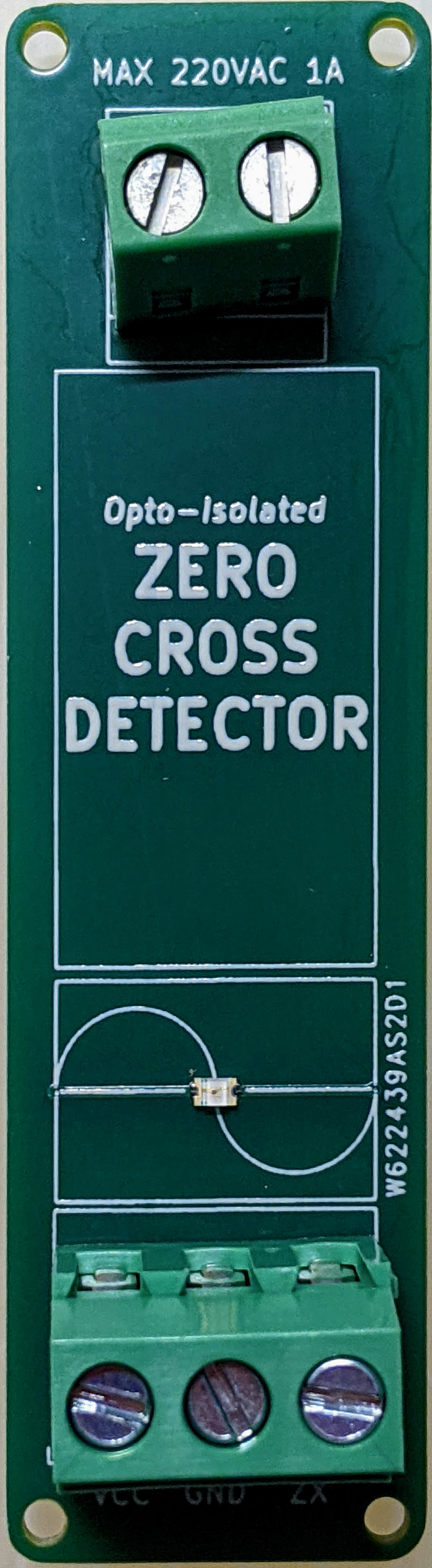
The Zero-Cross Detector by Dan TStar (PCBWay) is a specialized circuit designed to detect the precise moment when an alternating current (AC) signal crosses zero volts. This functionality is critical in applications requiring phase synchronization, such as dimmer circuits, motor speed controllers, and timing-sensitive systems. By providing a clean and reliable zero-crossing signal, this component ensures accurate phase control and synchronization in AC systems.
Explore Projects Built with Zero-Cross Detector


Explore Projects Built with Zero-Cross Detector
Common Applications and Use Cases
- Phase control in light dimmers
- Motor speed control in industrial applications
- Timing reference for microcontroller-based systems
- Synchronization in power electronics
- AC signal monitoring and analysis
Technical Specifications
The Zero-Cross Detector is designed to operate efficiently in a variety of AC systems. Below are its key technical details:
General Specifications
| Parameter | Value |
|---|---|
| Input Voltage Range | 90V AC to 250V AC |
| Output Signal | 5V DC pulse (TTL compatible) |
| Output Pulse Width | 1 ms |
| Operating Temperature | -20°C to 70°C |
| Power Consumption | < 0.5W |
| Isolation | Optocoupler-based isolation |
Pin Configuration and Descriptions
| Pin Number | Pin Name | Description |
|---|---|---|
| 1 | AC_IN1 | First AC input terminal (connect to one side of the AC line) |
| 2 | AC_IN2 | Second AC input terminal (connect to the other side of the AC line) |
| 3 | GND | Ground connection for the output circuit |
| 4 | VCC | Power supply for the output circuit (typically 5V DC) |
| 5 | OUT | Zero-cross detection output (5V pulse) |
Usage Instructions
How to Use the Component in a Circuit
- Connect the AC Input:
- Connect the AC_IN1 and AC_IN2 pins to the AC signal you want to monitor. Ensure proper insulation and safety precautions when working with high-voltage AC signals.
- Power the Circuit:
- Provide a 5V DC supply to the VCC pin and connect the GND pin to the ground of your system.
- Read the Output:
- The OUT pin will generate a 5V pulse every time the AC signal crosses zero volts. This pulse can be fed into a microcontroller or other digital logic circuits for further processing.
Important Considerations and Best Practices
- Safety First: Always handle AC connections with care. Use proper insulation and avoid direct contact with live wires.
- Isolation: The circuit uses optocoupler-based isolation to protect the low-voltage side from high-voltage AC. Ensure the optocoupler is functioning correctly.
- Filtering: If the output signal is noisy, consider adding a small capacitor (e.g., 0.1 µF) between the OUT pin and GND to filter out high-frequency noise.
- Microcontroller Compatibility: The 5V output pulse is TTL compatible, making it suitable for direct interfacing with most microcontrollers, including Arduino.
Example: Using with Arduino UNO
Below is an example of how to use the Zero-Cross Detector with an Arduino UNO to detect zero-crossing events and toggle an LED:
// Pin definitions
const int zeroCrossPin = 2; // Connect OUT pin of Zero-Cross Detector to pin 2
const int ledPin = 13;      // Onboard LED pin

void setup() {
  pinMode(zeroCrossPin, INPUT); // Set zero-cross pin as input
  pinMode(ledPin, OUTPUT);      // Set LED pin as output
  attachInterrupt(digitalPinToInterrupt(zeroCrossPin), zeroCrossDetected, RISING);
  // Attach an interrupt to detect rising edge of zero-cross signal
}

void loop() {
  // Main loop does nothing; zero-cross events are handled in the interrupt
}

void zeroCrossDetected() {
  digitalWrite(ledPin, HIGH); // Turn on LED when zero-cross is detected
  delay(50);                  // Keep LED on for 50ms (for visibility)
  digitalWrite(ledPin, LOW);  // Turn off LED
}
Troubleshooting and FAQs
Common Issues and Solutions
No Output Signal:
- Cause: Incorrect AC input connection or insufficient power supply.
- Solution: Verify that the AC_IN1 and AC_IN2 pins are connected to a live AC signal. Ensure the VCC pin is supplied with 5V DC.
Output Signal is Noisy:
- Cause: Electrical noise or interference in the AC line.
- Solution: Add a small capacitor (e.g., 0.1 µF) between the OUT pin and GND to filter noise.
Microcontroller Not Detecting Signal:
- Cause: Incorrect pin configuration or incompatible voltage levels.
- Solution: Ensure the OUT pin is connected to a digital input pin on the microcontroller. Verify that the microcontroller is configured to detect a rising edge.
Component Overheating:
- Cause: Excessive current draw or incorrect connections.
- Solution: Check all connections and ensure the component is not exposed to voltages or currents beyond its rated specifications.
FAQs
Q1: Can this component be used with 3.3V microcontrollers?
A1: Yes, but you may need a voltage divider or level shifter to step down the 5V output signal to 3.3V.
Q2: Is the Zero-Cross Detector suitable for DC signals?
A2: No, this component is specifically designed for AC signals and will not function with DC inputs.
Q3: Can I use this component for 50Hz and 60Hz AC systems?
A3: Yes, the Zero-Cross Detector is compatible with both 50Hz and 60Hz AC frequencies.
Q4: What is the purpose of the optocoupler in this circuit?
A4: The optocoupler provides electrical isolation between the high-voltage AC side and the low-voltage output side, ensuring safety and protecting sensitive components.
By following this documentation, you can effectively integrate the Dan TStar (PCBWay) Zero-Cross Detector into your projects for reliable and accurate zero-cross detection.