How to Use RPLIDAR A1M8: Examples, Pinouts, and Specs
Introduction
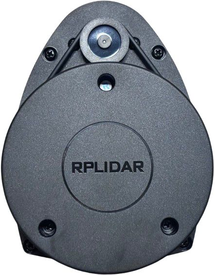
The RPLIDAR A1M8, manufactured by Slamtec, is a 360-degree laser scanner designed for high-resolution distance measurements. It is widely used in robotics, autonomous vehicles, and other applications requiring precise mapping and navigation. By emitting laser pulses and analyzing their reflections, the RPLIDAR A1M8 generates detailed 2D maps of its surroundings, making it an essential tool for SLAM (Simultaneous Localization and Mapping) systems.
Explore Projects Built with RPLIDAR A1M8
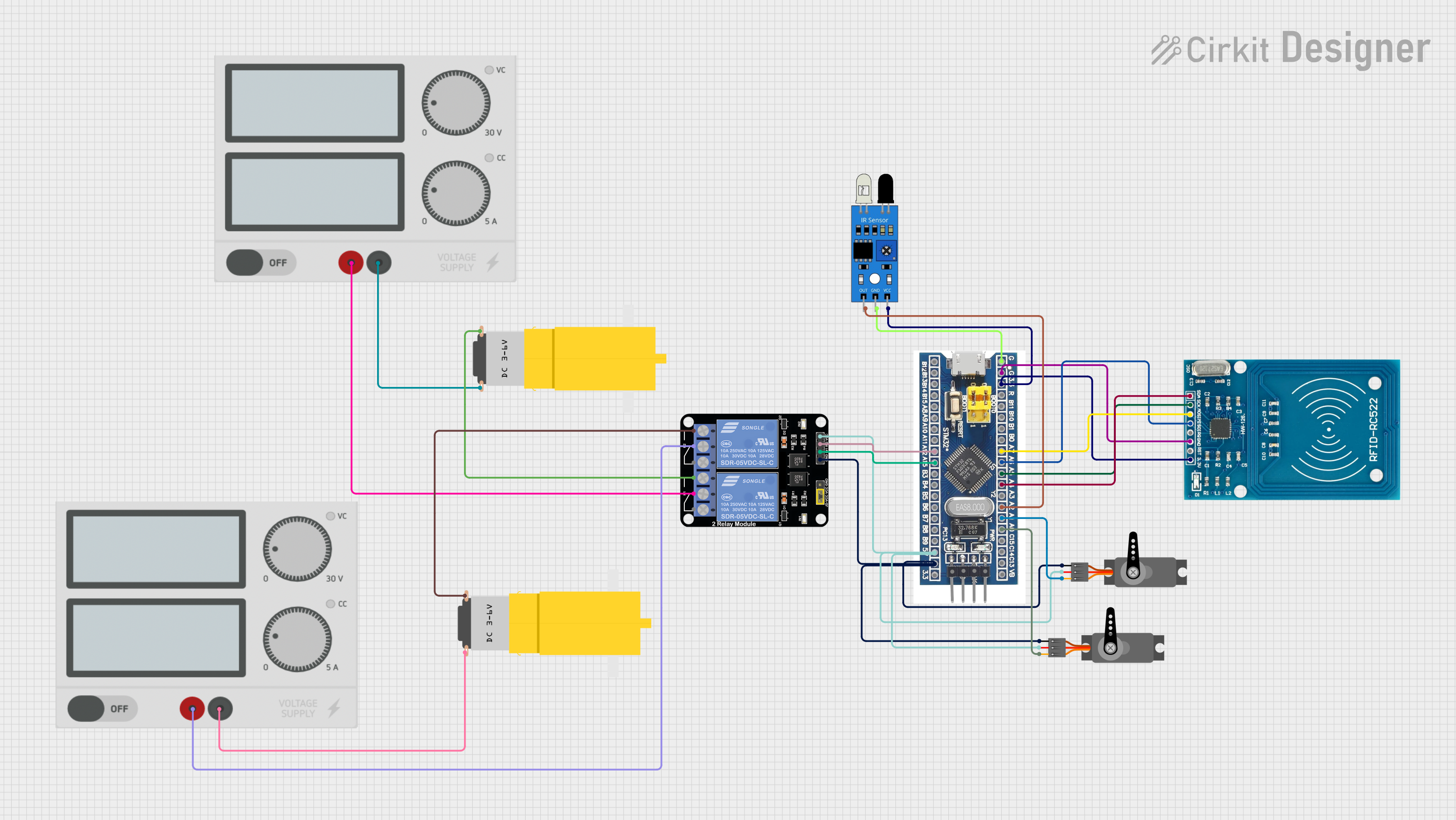

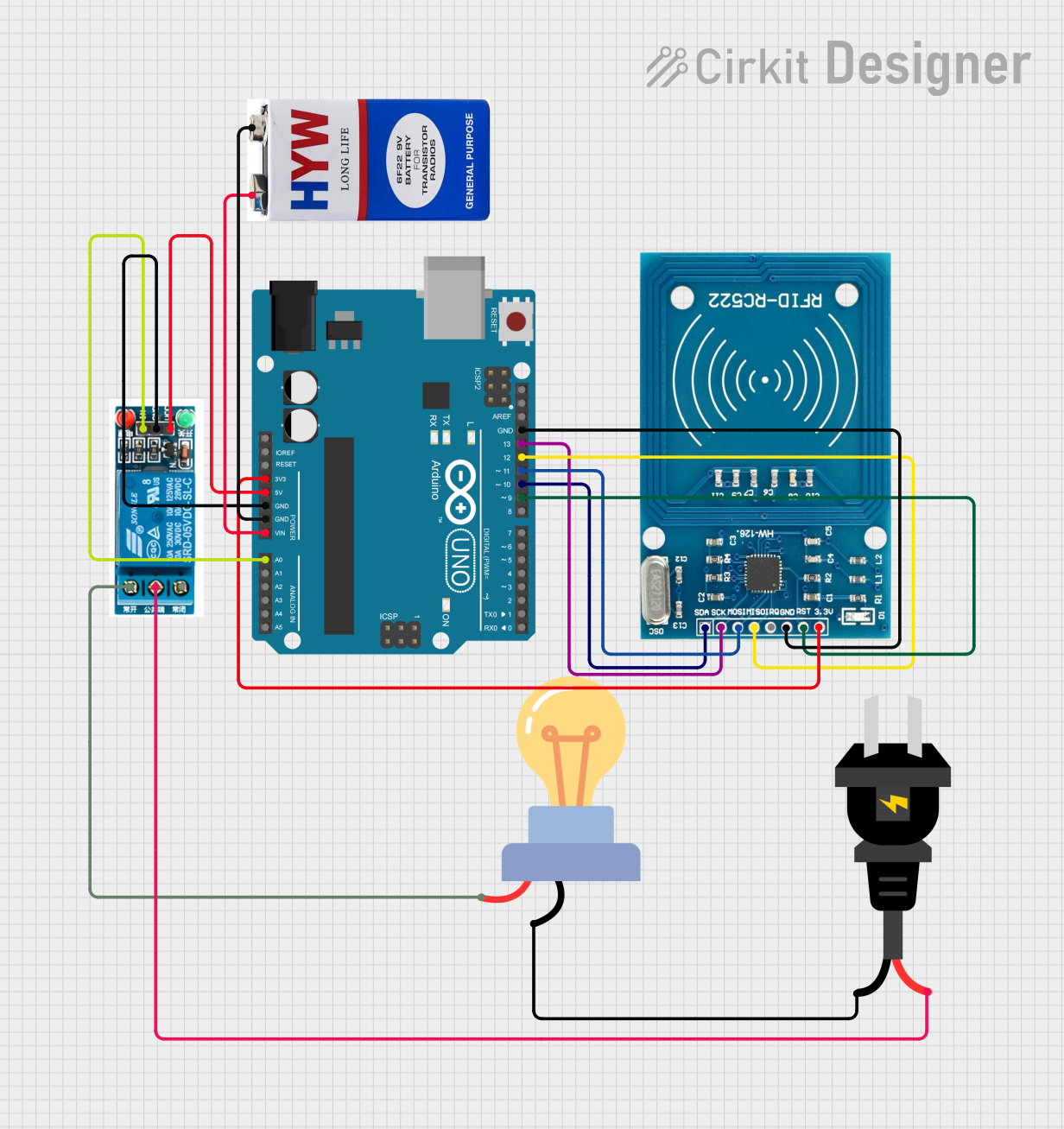
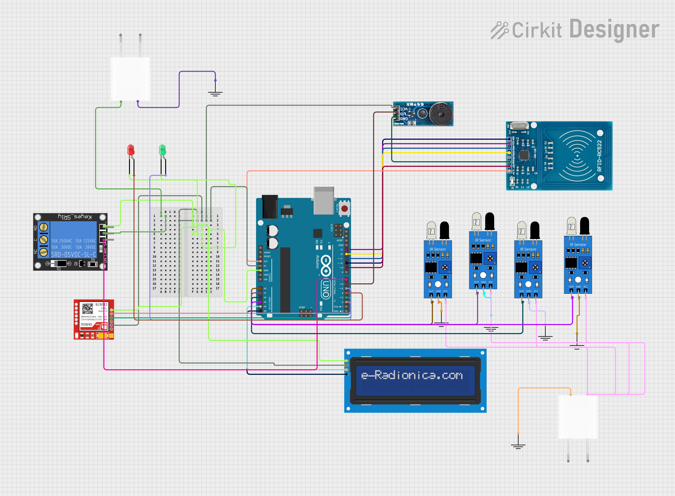
Explore Projects Built with RPLIDAR A1M8
Common Applications
- Robotics navigation and obstacle avoidance
- Autonomous vehicle mapping
- Indoor and outdoor 2D mapping
- Industrial automation and monitoring
- Research and development in SLAM technologies
Technical Specifications
The RPLIDAR A1M8 is a compact and efficient lidar sensor with the following key specifications:
| Parameter | Value |
|---|---|
| Measurement Range | 0.15 m to 12 m |
| Scanning Frequency | 5 Hz to 10 Hz |
| Angular Resolution | 1° to 0.5° (adjustable) |
| Distance Resolution | < 1% of the distance |
| Laser Wavelength | 785 nm (infrared) |
| Laser Safety | Class 1 (eye-safe) |
| Communication Interface | UART (3.3V TTL) |
| Input Voltage | 5 V DC |
| Power Consumption | 2 W (typical) |
| Operating Temperature | 0°C to 40°C |
| Dimensions | 98.5 mm × 70 mm × 60 mm |
| Weight | 190 g |
Pin Configuration and Descriptions
The RPLIDAR A1M8 uses a 5-pin interface for power and communication. The pinout is as follows:
| Pin | Name | Description |
|---|---|---|
| 1 | VCC | Power input (5 V DC) |
| 2 | GND | Ground |
| 3 | TX | UART Transmit (3.3V TTL) |
| 4 | RX | UART Receive (3.3V TTL) |
| 5 | MOTOR_CTRL_PWM | Motor speed control (PWM input, optional) |
Usage Instructions
Connecting the RPLIDAR A1M8
- Power Supply: Connect the VCC pin to a 5V DC power source and the GND pin to ground.
- Communication: Use the TX and RX pins to establish a UART connection with a microcontroller or computer. Ensure the UART voltage level is 3.3V TTL.
- Motor Control (Optional): If you need to control the motor speed, connect the MOTOR_CTRL_PWM pin to a PWM-capable pin on your microcontroller.
Using the RPLIDAR A1M8 with Arduino UNO
To interface the RPLIDAR A1M8 with an Arduino UNO, you will need a USB-to-TTL adapter or a hardware UART module, as the Arduino UNO has only one hardware UART port. Below is an example of how to use the RPLIDAR A1M8 with Arduino:
Required Libraries
Download and install the RPLIDAR Arduino Library from GitHub.
Example Code
#include <RPLidar.h>

// Define the RPLIDAR object
RPLidar lidar;

// Define the pins for the RPLIDAR
#define RPLIDAR_RX 10  // RX pin connected to RPLIDAR TX
#define RPLIDAR_TX 11  // TX pin connected to RPLIDAR RX

void setup() {
  Serial.begin(115200); // Initialize serial communication for debugging
  lidar.begin(Serial1); // Initialize RPLIDAR communication on Serial1

  // Start the RPLIDAR motor
  if (lidar.startMotor()) {
    Serial.println("RPLIDAR motor started successfully.");
  } else {
    Serial.println("Failed to start RPLIDAR motor.");
  }
}

void loop() {
  // Check if a new scan is available
  if (IS_OK(lidar.waitPoint())) {
    float distance = lidar.getCurrentPoint().distance; // Get distance in mm
    float angle = lidar.getCurrentPoint().angle;       // Get angle in degrees

    // Print the distance and angle to the Serial Monitor
    Serial.print("Distance: ");
    Serial.print(distance);
    Serial.print(" mm, Angle: ");
    Serial.print(angle);
    Serial.println(" degrees");
  } else {
    Serial.println("Failed to retrieve scan data.");
  }
}
Important Considerations
- Power Supply: Ensure a stable 5V power source to avoid performance issues.
- UART Voltage Levels: Use a level shifter if your microcontroller operates at 5V logic levels.
- Motor Control: The motor speed can be adjusted using a PWM signal, but it is optional for most applications.
- Environment: Avoid using the RPLIDAR A1M8 in environments with direct sunlight or reflective surfaces, as these can interfere with laser measurements.
Troubleshooting and FAQs
Common Issues
No Data Output:
- Ensure the TX and RX pins are correctly connected.
- Verify that the UART baud rate matches the RPLIDAR's default (115200 bps).
- Check the power supply voltage and current.
Inaccurate Measurements:
- Ensure the RPLIDAR is placed on a stable surface.
- Avoid reflective or transparent objects in the scanning area.
Motor Not Spinning:
- Verify the MOTOR_CTRL_PWM pin is connected (if using manual motor control).
- Check the power supply to ensure sufficient current.
Device Overheating:
- Ensure proper ventilation around the RPLIDAR.
- Avoid prolonged operation in high-temperature environments.
FAQs
Q: Can the RPLIDAR A1M8 be used outdoors?
A: Yes, but it performs best in controlled lighting conditions. Direct sunlight may reduce accuracy.
Q: What is the maximum scanning range?
A: The RPLIDAR A1M8 can measure distances up to 12 meters.
Q: Is the laser safe for human eyes?
A: Yes, the RPLIDAR A1M8 uses a Class 1 laser, which is eye-safe under normal operating conditions.
Q: Can I use the RPLIDAR A1M8 with a Raspberry Pi?
A: Yes, the RPLIDAR A1M8 can be connected to a Raspberry Pi via its UART interface. Use the appropriate libraries for integration.
Q: How do I clean the RPLIDAR lens?
A: Use a soft, lint-free cloth to gently clean the lens. Avoid using abrasive materials or liquids.
By following this documentation, you can effectively integrate and operate the RPLIDAR A1M8 in your projects.