How to Use voltamp meter: Examples, Pinouts, and Specs
Introduction
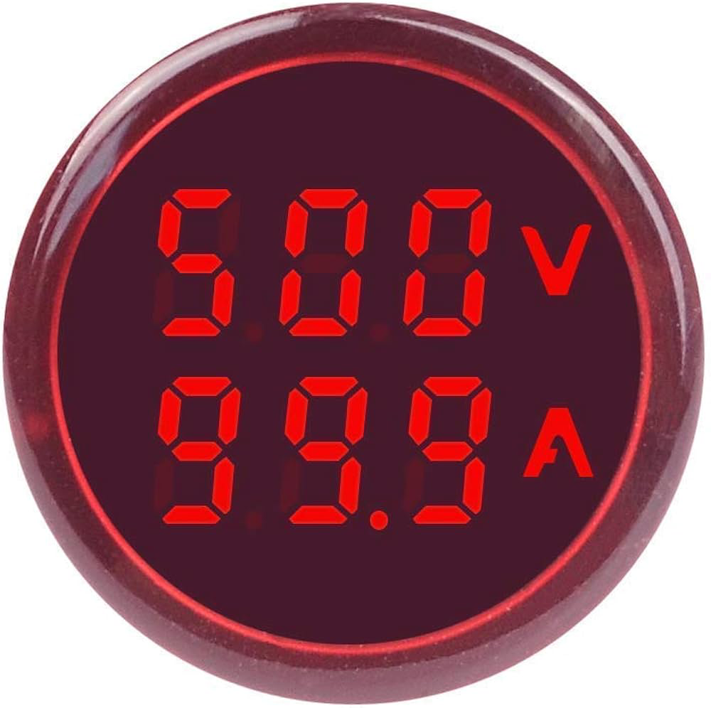
A Voltamp Meter, also known as a multimeter or V-A meter, is an essential instrument in electronics that measures both voltage (volts) and current (amperes) in an electrical circuit. This versatile tool is widely used in various applications, from simple home DIY projects to complex industrial systems, for troubleshooting, testing, and designing electrical and electronic circuits.
Explore Projects Built with voltamp meter
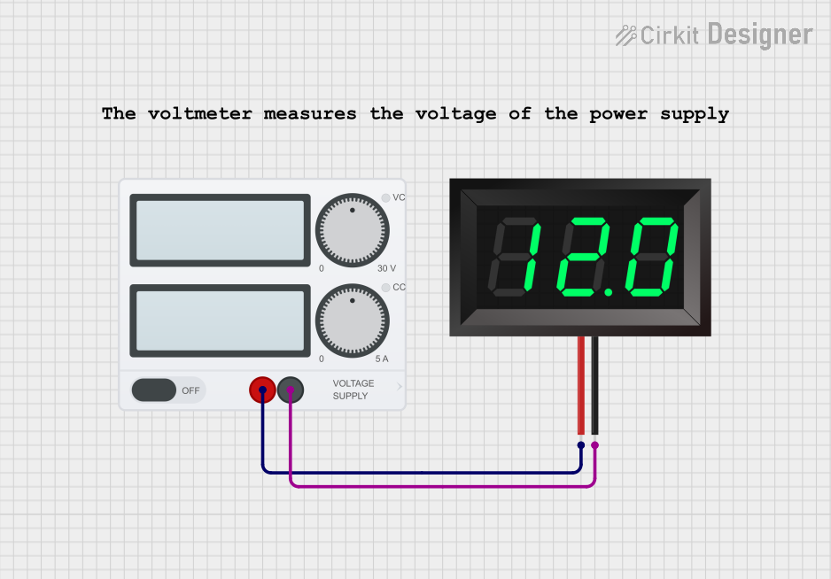
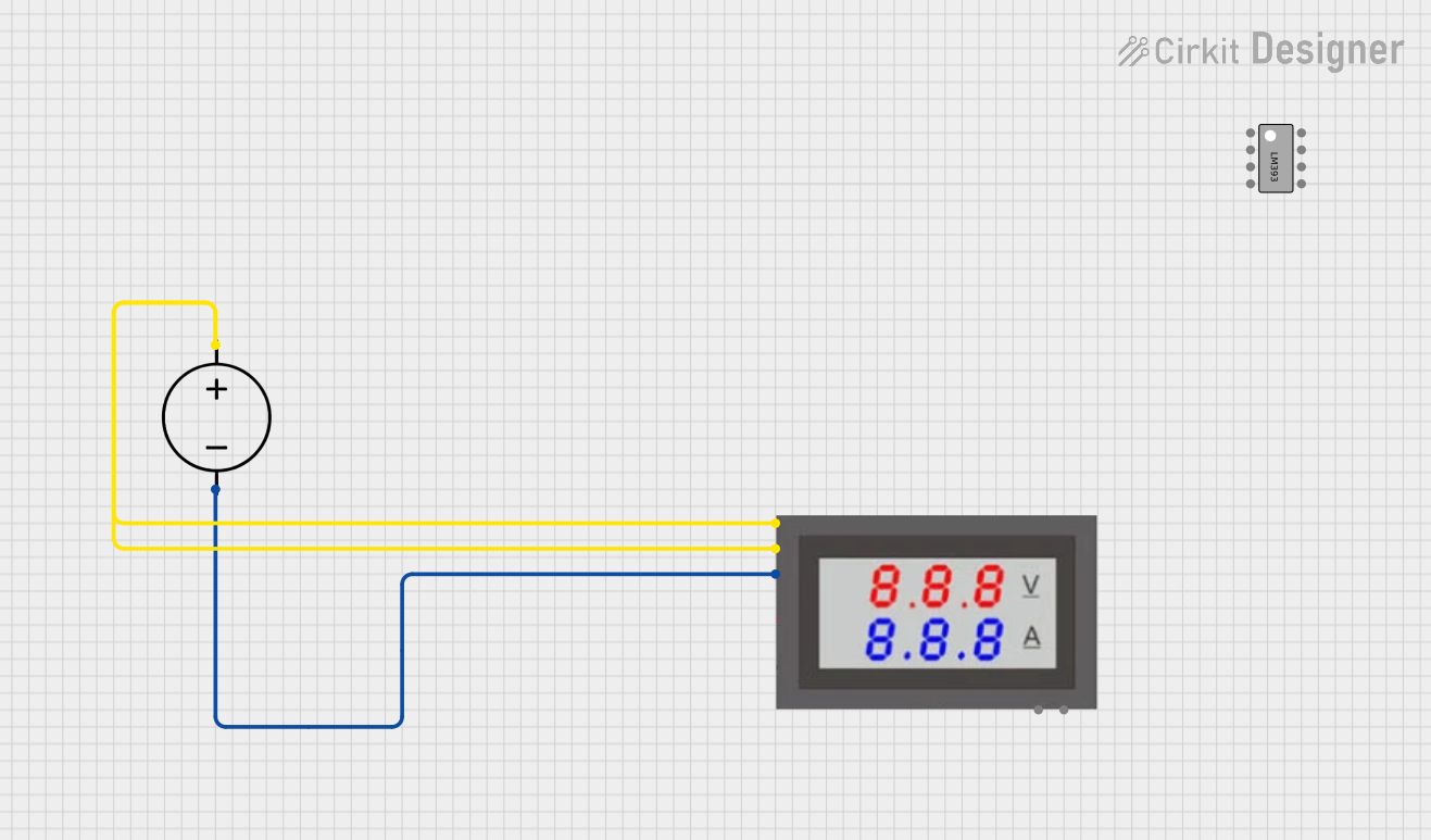
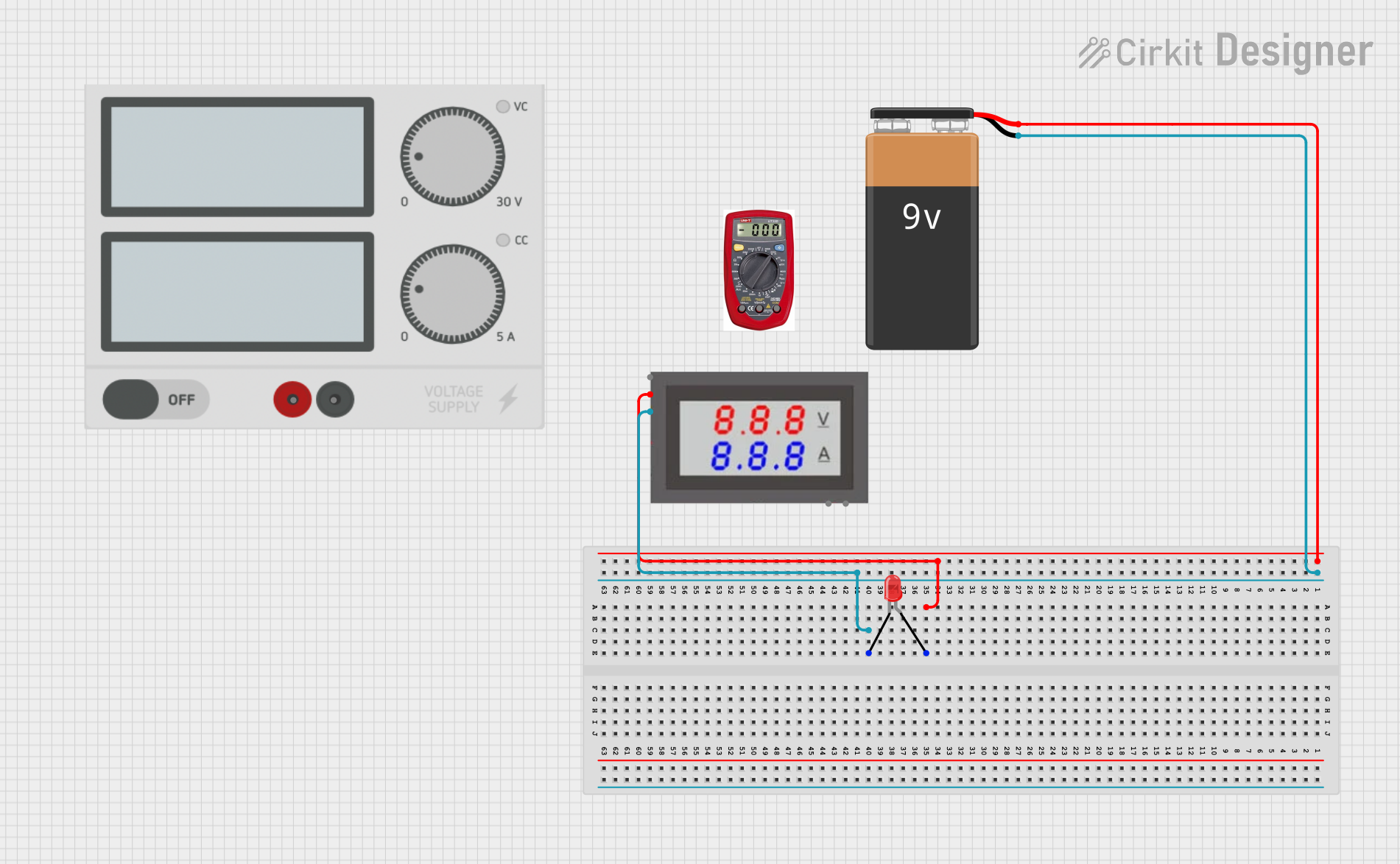

Explore Projects Built with voltamp meter
Common Applications and Use Cases
- Electrical Maintenance: Checking batteries, power supplies, and electrical outlets.
- Circuit Design and Testing: Verifying the performance of circuits during prototyping.
- Automotive: Diagnosing electrical issues in vehicles.
- Education: Teaching students about electrical principles and circuit analysis.
Technical Specifications
Key Technical Details
| Specification | Value/Description |
|---|---|
| Voltage Range | 0 - 600V AC/DC |
| Current Range | 0 - 10A AC/DC |
| Accuracy | ±(0.5% + 1 digit) |
| Display | LCD, 4000 counts |
| Frequency Range | 0 - 60MHz |
| Resistance Range | 0 - 40MΩ |
| Capacitance Range | 0 - 100μF |
| Temperature Range | -20°C to 1000°C |
| Power Supply | 9V Battery |
Pin Configuration and Descriptions
| Pin/Socket | Description |
|---|---|
| COM | Common ground for all measurements |
| VΩmA | Voltage, resistance, and small current measurements |
| 10A | High current measurements (up to 10A) |
Usage Instructions
How to Use the Component in a Circuit
Connecting the Probes:
- Connect the black probe to the COM socket.
- Connect the red probe to the VΩmA socket for voltage, resistance, or small current measurements.
- For current measurements greater than 200mA, use the 10A socket.
Setting the Measurement Type:
- Turn the dial to the desired measurement type (e.g., V for voltage, A for current).
Taking a Measurement:
- For voltage: Touch the probes to the two points between which you want to measure voltage.
- For current: Break the circuit and connect the meter in series so that the current flows through the meter.
Reading the Display:
- Read the measurement value from the LCD display.
Important Considerations and Best Practices
- Always start with the highest range of measurement and work your way down to avoid damaging the meter.
- When measuring current, ensure the circuit power is off before connecting the meter in series.
- Do not use the meter on circuits that exceed its maximum ratings.
- Regularly check and replace the battery to ensure accurate readings.
Troubleshooting and FAQs
Common Issues
- Inaccurate Readings: Ensure the battery is good and the probes are properly connected.
- No Reading: Check if the meter is set to the correct measurement type and range.
- Overload Indicator (OL): The measured value exceeds the meter's capability. Switch to a higher range.
Solutions and Tips for Troubleshooting
- If the meter does not power on, replace the battery.
- Ensure the probes are not damaged and are making good contact with the test points.
- Always start with the assumption that the circuit is live. Use appropriate safety measures.
FAQs
Q: Can I measure AC and DC with the same settings? A: No, you must select the correct AC or DC setting on the meter before measuring.
Q: What does the 'COM' socket mean? A: 'COM' stands for common and is the ground reference for all measurements.
Q: How do I measure high currents? A: Use the 10A socket and set the meter to the appropriate current range.
Q: Can the Voltamp Meter measure capacitance? A: Yes, if the meter has a capacitance range, it can measure capacitance.
Example Code for Arduino UNO Connection
// Example code for reading voltage using an Arduino UNO and a voltage sensor module
int analogInput = A0; // Connect voltage sensor output to analog pin A0
float vOut = 0.0;
float vIn = 0.0;
float R1 = 30000.0; // resistance of R1 (30k)
float R2 = 7500.0;  // resistance of R2 (7.5k)
int value = 0;

void setup(){
   pinMode(analogInput, INPUT);
   Serial.begin(9600);
}

void loop(){
   // Read the analog input and convert it to voltage
   value = analogRead(analogInput);
   vOut = (value * 5.0) / 1024.0; // convert the analog reading (which goes from 0 - 1023) to a voltage (0 - 5V)
   vIn = vOut / (R2/(R1+R2));
   if (vIn < 0.09) {
     vIn = 0.0; // statement to quash undesired reading !
   }
   Serial.print("INPUT V= ");
   Serial.println(vIn);
   delay(500);
}
Note: The above code is for a simple voltage divider circuit connected to an Arduino UNO. The actual connection to a Voltamp Meter would depend on the specific module or shield designed for use with an Arduino. Always refer to the manufacturer's datasheet for accurate connection and usage with microcontrollers.