How to Use INA 114: Examples, Pinouts, and Specs
Introduction
The INA114 is a precision instrumentation amplifier manufactured by Texas Instruments (Part ID: IC). It is designed for low-level signal amplification, offering high input impedance, low offset voltage, and low noise. These features make it an excellent choice for applications requiring accurate and stable signal processing, such as medical instrumentation, sensor signal conditioning, and data acquisition systems.
Explore Projects Built with INA 114

Explore Projects Built with INA 114
Common Applications:
- Medical instrumentation (e.g., ECG, EEG)
- Sensor signal conditioning
- Data acquisition systems
- Industrial process controls
- Strain gauge amplifiers
Technical Specifications
Key Specifications:
- Supply Voltage Range: ±2.25V to ±18V
- Input Impedance: 10⁹ Ω (typical)
- Gain Range: 1 to 10,000 (set by external resistor)
- Offset Voltage: 50 µV (typical)
- Input Noise Voltage: 8 nV/√Hz at 1 kHz
- Common-Mode Rejection Ratio (CMRR): 115 dB (typical)
- Bandwidth: 1.5 MHz (at G = 1)
- Operating Temperature Range: -40°C to +85°C
- Package Type: 8-pin DIP or SOIC
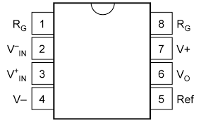
Pin Configuration and Descriptions:
The INA114 is an 8-pin device. Below is the pinout and description:
| Pin Number | Pin Name | Description |
|---|---|---|
| 1 | RG | Gain-setting resistor connection (connect external resistor to set gain) |
| 2 | -IN | Inverting input |
| 3 | +IN | Non-inverting input |
| 4 | V- | Negative power supply |
| 5 | Ref | Reference voltage input (sets output reference level, typically connected to GND) |
| 6 | Output | Amplifier output |
| 7 | V+ | Positive power supply |
| 8 | RG | Gain-setting resistor connection (connect external resistor to set gain) |
Usage Instructions
How to Use the INA114 in a Circuit:
- Power Supply: Connect the INA114 to a dual power supply (e.g., ±15V) or a single supply (e.g., 5V and GND). Ensure the supply voltage is within the specified range.
- Input Connections: Connect the signal source to the +IN (non-inverting) and -IN (inverting) pins. Use shielded cables for low-noise applications.
- Gain Setting: Use an external resistor between the RG pins (pins 1 and 8) to set the desired gain. The gain is calculated as: [ G = 1 + \frac{50k\Omega}{R_G} ] For example, if ( R_G = 10k\Omega ), the gain will be ( G = 6 ).
- Reference Pin: Connect the Ref pin (pin 5) to ground or a reference voltage to set the output reference level.
- Output: The amplified signal will be available at the Output pin (pin 6). Connect this to the next stage of your circuit.
Important Considerations:
- Use precision resistors for the gain-setting resistor ( R_G ) to ensure accurate gain.
- Decouple the power supply with capacitors (e.g., 0.1 µF ceramic and 10 µF electrolytic) close to the V+ and V- pins to reduce noise.
- Avoid exceeding the input voltage range to prevent damage or incorrect operation.
- For optimal performance, ensure the input signals are within the common-mode voltage range.
Example: Connecting the INA114 to an Arduino UNO
The INA114 can be used to amplify low-level signals (e.g., from a sensor) for input to an Arduino UNO's analog pin. Below is an example circuit and code:
Circuit:
- Connect the INA114's V+ to +5V and V- to GND.
- Connect the sensor's output to the +IN pin and GND to the -IN pin.
- Set the gain using an external resistor ( R_G ).
- Connect the Output pin to an Arduino analog input (e.g., A0).
- Connect the Ref pin to GND.
Arduino Code:
// INA114 Amplifier Example with Arduino UNO
// Reads the amplified signal from the INA114 and displays it via Serial Monitor

const int analogPin = A0; // Analog pin connected to INA114 Output

void setup() {
  Serial.begin(9600); // Initialize serial communication at 9600 baud
}

void loop() {
  int sensorValue = analogRead(analogPin); // Read the analog value (0-1023)

  // Convert the analog value to voltage (assuming 5V reference)
  float voltage = sensorValue * (5.0 / 1023.0);

  // Print the voltage to the Serial Monitor
  Serial.print("Amplified Voltage: ");
  Serial.print(voltage);
  Serial.println(" V");

  delay(500); // Wait for 500ms before the next reading
}
Troubleshooting and FAQs
Common Issues and Solutions:
No Output Signal:
- Verify the power supply connections and ensure the voltage is within the specified range.
- Check the input signal and ensure it is within the common-mode voltage range.
- Ensure the gain-setting resistor ( R_G ) is properly connected.
Output Signal is Saturated:
- Reduce the input signal amplitude or decrease the gain by increasing ( R_G ).
- Check the Ref pin voltage and ensure it is correctly set.
High Noise in Output:
- Use shielded cables for input connections.
- Add decoupling capacitors to the power supply pins.
- Ensure proper grounding in the circuit.
Incorrect Gain:
- Verify the value of the gain-setting resistor ( R_G ).
- Use precision resistors to minimize errors.
FAQs:
Can the INA114 operate with a single power supply? Yes, the INA114 can operate with a single supply, but the input and output signals must remain within the specified voltage range.
What is the maximum gain I can achieve with the INA114? The maximum gain is determined by the external resistor ( R_G ). With a very small ( R_G ), gains up to 10,000 are possible, but stability and bandwidth may be affected.
Can I use the INA114 for AC signals? Yes, the INA114 can amplify AC signals. Use coupling capacitors if needed to block DC components.
What is the purpose of the Ref pin? The Ref pin sets the output reference voltage. For single-supply operation, it is often set to half the supply voltage to allow the output to swing both above and below this level.
By following this documentation, users can effectively integrate the INA114 into their designs for precise and reliable signal amplification.