
How to Use ATMEGA8U2: Examples, Pinouts, and Specs
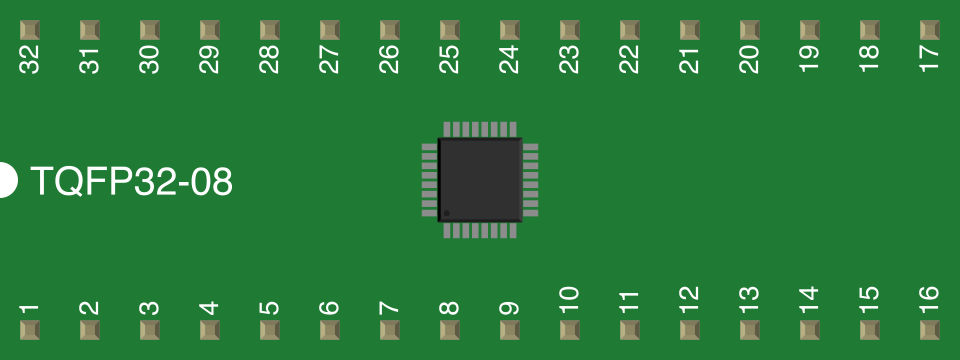
 Design with ATMEGA8U2 in Cirkit Designer
Introduction
The ATmega8U2 is an 8-bit microcontroller from Microchip Technology's AVR family. It features 8KB of flash memory, 1KB of SRAM, and 256 bytes of EEPROM. One of its standout features is its built-in USB communication capability, making it ideal for applications requiring USB interfacing. The ATmega8U2 is widely used in embedded systems for tasks such as device control, data processing, and USB-to-serial communication.
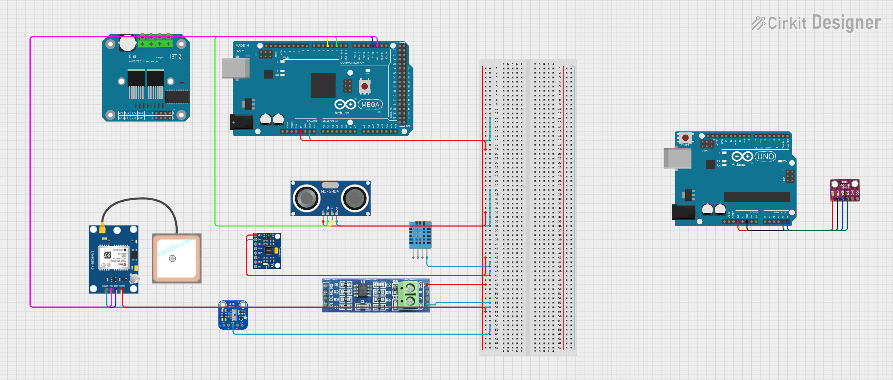
Explore Projects Built with ATMEGA8U2
 Open Project in Cirkit Designer
 Open Project in Cirkit Designer
 Open Project in Cirkit Designer
 Open Project in Cirkit Designer
Explore Projects Built with ATMEGA8U2
Open Project in Cirkit DesignerOpen Project in Cirkit DesignerOpen Project in Cirkit DesignerOpen Project in Cirkit DesignerCommon Applications
- USB-to-serial converters
- Embedded systems requiring USB communication
- Custom USB devices (e.g., keyboards, mice, or game controllers)
- Prototyping and development boards (e.g., Arduino UNO R3)
Technical Specifications
Key Technical Details
| Parameter | Value |
|---|---|
| Architecture | 8-bit AVR |
| Flash Memory | 8KB |
| SRAM | 1KB |
| EEPROM | 256 bytes |
| Operating Voltage | 2.7V - 5.5V |
| Maximum Clock Speed | 16 MHz |
| USB Support | Full-Speed USB 2.0 |
| I/O Pins | 22 |
| ADC Channels | None |
| Communication Interfaces | USB, USART, SPI |
| Package Type | TQFP-32, QFN-32 |
Pin Configuration and Descriptions
The ATmega8U2 is available in a 32-pin package. Below is the pin configuration:
| Pin Number | Pin Name | Description |
|---|---|---|
| 1 | PC6 | General-purpose I/O |
| 2 | PD0 | USART RXD (Receive Data) |
| 3 | PD1 | USART TXD (Transmit Data) |
| 4 | PD2 | General-purpose I/O |
| 5 | PD3 | General-purpose I/O |
| 6 | PD4 | General-purpose I/O |
| 7 | VCC | Power Supply (2.7V - 5.5V) |
| 8 | GND | Ground |
| 9 | XTAL1 | External Oscillator Input |
| 10 | XTAL2 | External Oscillator Output |
| 11 | RESET | Reset Pin (Active Low) |
| 12 | PB0 | General-purpose I/O |
| 13 | PB1 | General-purpose I/O |
| 14 | PB2 | General-purpose I/O |
| 15 | PB3 | General-purpose I/O |
| 16 | PB4 | General-purpose I/O |
| 17 | PB5 | General-purpose I/O |
| 18 | PB6 | General-purpose I/O |
| 19 | PB7 | General-purpose I/O |
| 20 | AVCC | Analog Power Supply |
| 21 | GND | Ground |
| 22 | PC0 | General-purpose I/O |
| 23 | PC1 | General-purpose I/O |
| 24 | PC2 | General-purpose I/O |
| 25 | PC3 | General-purpose I/O |
| 26 | PC4 | General-purpose I/O |
| 27 | PC5 | General-purpose I/O |
| 28 | PD5 | General-purpose I/O |
| 29 | PD6 | General-purpose I/O |
| 30 | PD7 | General-purpose I/O |
| 31 | VBUS | USB Power Supply |
| 32 | D- | USB Data Negative |
| 33 | D+ | USB Data Positive |
Usage Instructions
Using the ATmega8U2 in a Circuit
- Power Supply: Connect the VCC pin to a regulated power source (2.7V to 5.5V) and GND to ground.
- Clock Source: Use an external crystal oscillator (e.g., 16 MHz) connected to XTAL1 and XTAL2 for stable operation.
- USB Communication: Connect the D+ and D- pins to a USB port for communication. Ensure proper pull-up resistors are used as per USB specifications.
- Programming: Use an ISP (In-System Programmer) or USB bootloader to upload firmware to the microcontroller.
- I/O Pins: Configure the I/O pins as input or output in the firmware, depending on the application.
Important Considerations
- USB Pull-Up Resistor: Ensure the USB D+ line has a 1.5kΩ pull-up resistor to indicate the device is connected.
- Decoupling Capacitors: Place 0.1µF decoupling capacitors close to the VCC and AVCC pins to reduce noise.
- Reset Circuit: Use a 10kΩ pull-up resistor on the RESET pin to prevent accidental resets.
- Firmware Development: Use AVR-GCC or Atmel Studio for writing and compiling firmware.
Example: USB-to-Serial Communication with Arduino UNO
The ATmega8U2 is used on the Arduino UNO R3 to handle USB-to-serial communication. Below is an example of how to send data from the Arduino to a PC via USB:
// Example: Sending data from Arduino UNO to PC via USB
void setup() {
  Serial.begin(9600); // Initialize USB serial communication at 9600 baud
}

void loop() {
  Serial.println("Hello, PC!"); // Send a message to the PC
  delay(1000); // Wait for 1 second
}
Troubleshooting and FAQs
Common Issues
USB Device Not Recognized:
- Cause: Incorrect USB wiring or missing pull-up resistor on D+.
- Solution: Verify the USB connections and ensure a 1.5kΩ pull-up resistor is present on the D+ line.
Microcontroller Not Responding:
- Cause: Incorrect power supply or faulty reset circuit.
- Solution: Check the VCC and GND connections. Ensure the RESET pin has a 10kΩ pull-up resistor.
Firmware Upload Fails:
- Cause: Incorrect ISP connections or bootloader issues.
- Solution: Verify the ISP connections and reflash the bootloader if necessary.
USB Communication Issues:
- Cause: Incorrect baud rate or firmware configuration.
- Solution: Ensure the baud rate in the firmware matches the PC settings.
FAQs
Q1: Can the ATmega8U2 be used without USB functionality?
Yes, the ATmega8U2 can function as a standalone microcontroller without using its USB features.
Q2: What is the maximum current draw of the ATmega8U2?
The maximum current draw is approximately 20mA per I/O pin, with a total limit of 200mA for all pins combined.
Q3: How do I program the ATmega8U2?
You can program the ATmega8U2 using an ISP programmer or via its USB bootloader if preloaded.
Q4: Does the ATmega8U2 support analog inputs?
No, the ATmega8U2 does not have ADC channels and does not support analog inputs.
Q5: Can I use the ATmega8U2 with Arduino IDE?
Yes, the ATmega8U2 is used on the Arduino UNO R3 for USB-to-serial communication, and you can program it using the Arduino IDE.