
How to Use LY530AL: Examples, Pinouts, and Specs
 Design with LY530AL in Cirkit Designer
Introduction
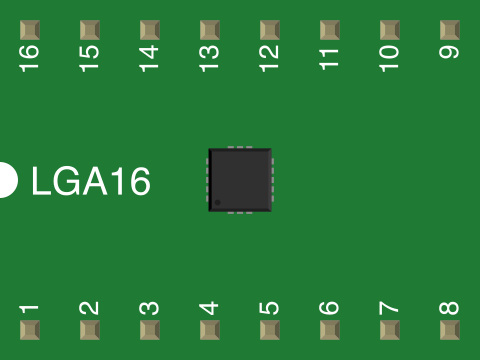
The LY530AL is a high-performance gyroscope sensor designed to measure angular velocity with precision. It is a single-axis gyroscope that operates on the principle of Coriolis force, making it ideal for detecting rotational motion. With its compact design, low power consumption, and high accuracy, the LY530AL is widely used in applications such as robotics, drones, motion tracking systems, and gaming devices. Its robust performance and ease of integration make it a popular choice for both hobbyists and professionals.
Explore Projects Built with LY530AL
 Open Project in Cirkit Designer
 Open Project in Cirkit Designer
 Open Project in Cirkit Designer
 Open Project in Cirkit Designer
Explore Projects Built with LY530AL
Open Project in Cirkit DesignerOpen Project in Cirkit DesignerOpen Project in Cirkit DesignerOpen Project in Cirkit DesignerTechnical Specifications
The following table outlines the key technical specifications of the LY530AL gyroscope sensor:
| Parameter | Value |
|---|---|
| Operating Voltage | 2.7V to 3.6V |
| Supply Current | 6.8 mA (typical) |
| Measurement Range | ±300°/s |
| Sensitivity | 3.33 mV/°/s |
| Bandwidth | 140 Hz |
| Operating Temperature Range | -40°C to +85°C |
| Output Type | Analog |
| Package Type | LGA-16 (4x4 mm) |
Pin Configuration and Descriptions
The LY530AL comes in a 16-pin LGA package. The table below describes the pin configuration:
| Pin Number | Pin Name | Description |
|---|---|---|
| 1 | Vdd | Power supply (2.7V to 3.6V) |
| 2 | GND | Ground |
| 3 | NC | Not connected (leave unconnected) |
| 4 | NC | Not connected (leave unconnected) |
| 5 | ST | Self-test pin (active high) |
| 6 | NC | Not connected (leave unconnected) |
| 7 | NC | Not connected (leave unconnected) |
| 8 | NC | Not connected (leave unconnected) |
| 9 | NC | Not connected (leave unconnected) |
| 10 | NC | Not connected (leave unconnected) |
| 11 | NC | Not connected (leave unconnected) |
| 12 | NC | Not connected (leave unconnected) |
| 13 | NC | Not connected (leave unconnected) |
| 14 | NC | Not connected (leave unconnected) |
| 15 | OUT | Angular velocity output (analog signal) |
| 16 | NC | Not connected (leave unconnected) |
Usage Instructions
How to Use the LY530AL in a Circuit
- Power Supply: Connect the Vdd pin to a stable power source within the range of 2.7V to 3.6V. Connect the GND pin to the ground of the circuit.
- Output Signal: The angular velocity is provided as an analog voltage on the OUT pin. Connect this pin to an analog input of a microcontroller or an ADC (Analog-to-Digital Converter) for further processing.
- Self-Test: To verify the functionality of the sensor, you can activate the self-test feature by applying a high signal to the ST pin. This will generate a known output signal for diagnostic purposes.
- Bypass Unused Pins: Leave all NC (Not Connected) pins unconnected to avoid interference.
Important Considerations and Best Practices
- Decoupling Capacitor: Place a 0.1 µF ceramic capacitor close to the Vdd pin to filter out noise and ensure stable operation.
- Mounting Orientation: Ensure the sensor is mounted correctly to align with the desired axis of rotation.
- Signal Conditioning: Use an operational amplifier or filter circuit if additional signal conditioning is required.
- Temperature Effects: Be aware of temperature variations, as they may slightly affect the sensor's output. Consider calibration if high precision is required.
Example Code for Arduino UNO
Below is an example of how to interface the LY530AL with an Arduino UNO to read the analog output:
// Define the analog pin connected to the OUT pin of the LY530AL
const int gyroPin = A0;

void setup() {
  // Initialize serial communication for debugging
  Serial.begin(9600);
}

void loop() {
  // Read the analog value from the gyroscope
  int gyroValue = analogRead(gyroPin);

  // Convert the analog value to voltage (assuming 5V reference)
  float voltage = gyroValue * (5.0 / 1023.0);

  // Calculate angular velocity in degrees per second
  // Sensitivity of LY530AL is 3.33 mV/°/s
  float angularVelocity = (voltage - 1.65) / 0.00333;

  // Print the angular velocity to the serial monitor
  Serial.print("Angular Velocity: ");
  Serial.print(angularVelocity);
  Serial.println(" °/s");

  // Small delay for stability
  delay(100);
}
Note: The above code assumes a 5V reference voltage for the Arduino UNO. If using a different reference voltage, adjust the calculation accordingly. The midpoint voltage (1.65V) corresponds to 0°/s angular velocity.
Troubleshooting and FAQs
Common Issues and Solutions
No Output Signal:
- Ensure the Vdd and GND pins are properly connected.
- Verify that the OUT pin is connected to an analog input or ADC.
- Check for loose or faulty connections.
Inaccurate Measurements:
- Confirm that the sensor is mounted correctly and aligned with the desired axis.
- Perform calibration to account for any offset or temperature effects.
- Use a stable power supply to minimize noise.
Self-Test Not Working:
- Ensure the ST pin is pulled high to activate the self-test feature.
- Verify the power supply voltage is within the specified range.
FAQs
Q: Can the LY530AL measure angular velocity on multiple axes?
A: No, the LY530AL is a single-axis gyroscope and can only measure angular velocity along one axis.
Q: What is the purpose of the self-test pin?
A: The self-test pin allows users to verify the functionality of the sensor by generating a known output signal.
Q: Can I use the LY530AL with a 5V microcontroller?
A: Yes, but you may need a voltage divider or level shifter to ensure the sensor's output is compatible with the microcontroller's input range.
Q: How do I reduce noise in the output signal?
A: Use a decoupling capacitor near the power supply pin and consider adding a low-pass filter to the output signal.