How to Use AD8318: Examples, Pinouts, and Specs
Introduction
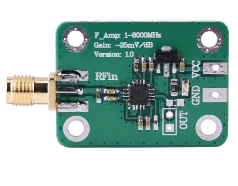
The AD8318 is a high-speed, low-cost logarithmic amplifier designed for RF and microwave applications. Manufactured by Arduino, this component is optimized for power detection and measurement in communication systems. It offers a wide dynamic range, fast response time, and excellent accuracy, making it ideal for applications such as RF power monitoring, signal strength indication, and automatic gain control (AGC) loops.
Explore Projects Built with AD8318


Explore Projects Built with AD8318
Common Applications and Use Cases
- RF and microwave power measurement
- Signal strength indication in communication systems
- Automatic gain control (AGC) loops
- Test and measurement equipment
- Wireless infrastructure (e.g., base stations)
- Radar and satellite communication systems
Technical Specifications
The AD8318 is a versatile component with the following key technical details:
Key Specifications
| Parameter | Value |
|---|---|
| Supply Voltage (Vcc) | 3.0 V to 5.5 V |
| Input Frequency Range | 1 MHz to 8 GHz |
| Dynamic Range | 70 dB (typical) |
| Response Time | 8 ns (typical) |
| Output Voltage Range | 0.5 V to 1.8 V (logarithmic) |
| Input Impedance | 50 Ω |
| Operating Temperature | -40°C to +85°C |
| Package Type | LFCSP (16-lead) |
Pin Configuration and Descriptions
The AD8318 is housed in a 16-lead LFCSP package. Below is the pin configuration and description:
| Pin Number | Pin Name | Description |
|---|---|---|
| 1 | VPOS | Positive supply voltage (3.0 V to 5.5 V). |
| 2 | COMM | Ground reference for the device. |
| 3 | INHI | RF input (high side). Connect to the RF signal source. |
| 4 | INLO | RF input (low side). Typically connected to ground through a capacitor. |
| 5 | FLTR | Filter pin for setting the response time. Connect a capacitor to ground. |
| 6 | VOUT | Logarithmic output voltage proportional to the input signal power. |
| 7 | VREF | Reference voltage output (1.8 V typical). |
| 8 | TEMP | Temperature sensor output. |
| 9-16 | NC | No connection. Leave these pins unconnected. |
Usage Instructions
The AD8318 is straightforward to use in RF power detection and measurement circuits. Below are the steps and considerations for integrating it into your design:
How to Use the AD8318 in a Circuit
- Power Supply: Connect the VPOS pin to a stable DC supply voltage between 3.0 V and 5.5 V. Connect the COMM pin to ground.
- RF Input: Feed the RF signal to the INHI pin. The INLO pin should typically be AC-coupled to ground using a capacitor.
- Output Filtering: Connect a capacitor to the FLTR pin to set the desired response time. A larger capacitor results in slower response but better noise filtering.
- Output Voltage: The VOUT pin provides a logarithmic voltage proportional to the input signal power. This can be read by an ADC or microcontroller for further processing.
- Temperature Monitoring: Use the TEMP pin to monitor the device's temperature if needed.
Important Considerations and Best Practices
- Input Matching: Ensure proper impedance matching (50 Ω) for optimal performance.
- Decoupling Capacitors: Place decoupling capacitors close to the VPOS pin to minimize noise.
- Thermal Management: Operate the device within the specified temperature range (-40°C to +85°C) to avoid performance degradation.
- Output Calibration: Calibrate the VOUT signal to account for variations in input power and frequency.
Example: Using the AD8318 with Arduino UNO
The AD8318 can be interfaced with an Arduino UNO to measure RF power. Below is an example code snippet:
// Example: Reading AD8318 output with Arduino UNO
// Connect AD8318 VOUT to Arduino A0 (analog input pin)

const int ad8318Pin = A0;  // Analog pin connected to AD8318 VOUT
float voltage = 0.0;       // Variable to store the measured voltage
float power_dBm = 0.0;     // Variable to store the calculated power in dBm

void setup() {
  Serial.begin(9600);  // Initialize serial communication
}

void loop() {
  // Read the analog voltage from AD8318
  int adcValue = analogRead(ad8318Pin);

  // Convert ADC value to voltage (assuming 5V reference and 10-bit ADC)
  voltage = (adcValue * 5.0) / 1023.0;

  // Convert voltage to power in dBm (calibration required for accuracy)
  // Example formula: power_dBm = (voltage - 0.5) * 50
  power_dBm = (voltage - 0.5) * 50.0;

  // Print the results to the Serial Monitor
  Serial.print("Voltage (V): ");
  Serial.print(voltage, 3);  // Print voltage with 3 decimal places
  Serial.print(" | Power (dBm): ");
  Serial.println(power_dBm, 2);  // Print power with 2 decimal places

  delay(500);  // Wait for 500 ms before the next reading
}
Troubleshooting and FAQs
Common Issues and Solutions
No Output Voltage:
- Ensure the VPOS pin is connected to a stable power supply.
- Verify that the RF signal is within the specified frequency range (1 MHz to 8 GHz).
- Check the connections to the INHI and INLO pins.
Inaccurate Power Measurement:
- Calibrate the VOUT signal for the specific input frequency and power range.
- Use a high-quality capacitor on the FLTR pin to reduce noise.
Excessive Noise on Output:
- Increase the value of the capacitor on the FLTR pin to improve filtering.
- Ensure proper grounding and shielding of the circuit.
Overheating:
- Verify that the device is operating within the specified temperature range.
- Check for excessive input power levels that may cause thermal stress.
FAQs
Q: Can the AD8318 measure negative RF power levels?
A: Yes, the AD8318 can measure low RF power levels down to -65 dBm, depending on the input frequency and calibration.
Q: What is the typical response time of the AD8318?
A: The typical response time is 8 ns, but this can be adjusted by changing the capacitor on the FLTR pin.
Q: Is the AD8318 suitable for battery-powered applications?
A: Yes, the AD8318 operates on a low supply voltage (3.0 V to 5.5 V) and consumes minimal power, making it suitable for battery-powered designs.
Q: How do I calibrate the output voltage for accurate power measurement?
A: Use a known RF signal source and measure the corresponding VOUT voltage. Create a calibration curve to map the voltage to power in dBm.
This concludes the documentation for the AD8318. For further assistance, refer to the manufacturer's datasheet or contact Arduino support.