
How to Use TTL TO 485: Examples, Pinouts, and Specs
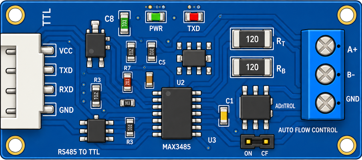
 Design with TTL TO 485 in Cirkit Designer
Introduction
The TTL to RS-485 converter is an electronic module designed to bridge the gap between TTL-level signals and RS-485 differential signals. This component enables seamless communication between TTL devices (e.g., microcontrollers, sensors) and RS-485 networks, which are widely used for long-distance, robust, and noise-resistant data transmission.
Explore Projects Built with TTL TO 485
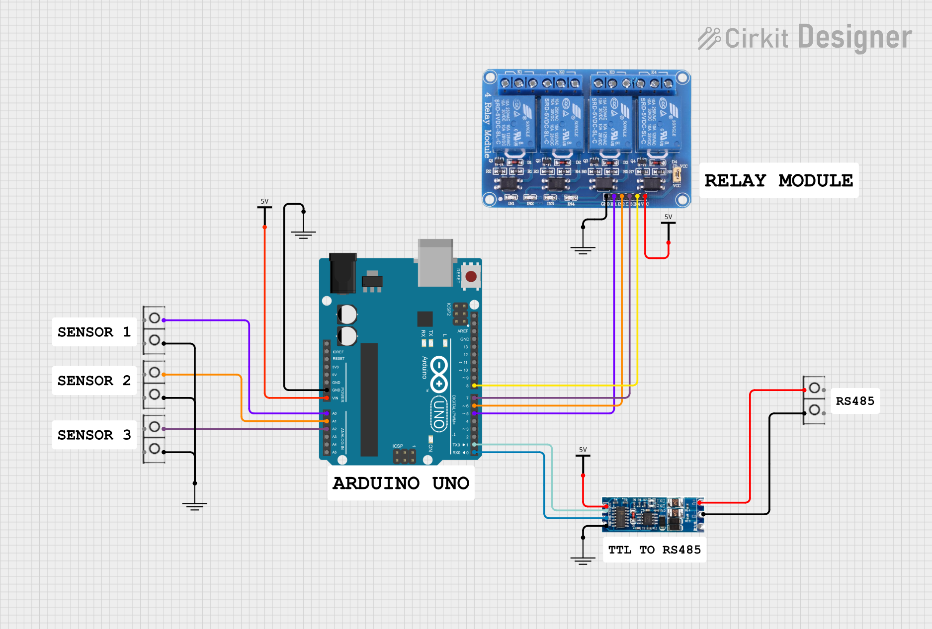 Open Project in Cirkit Designer
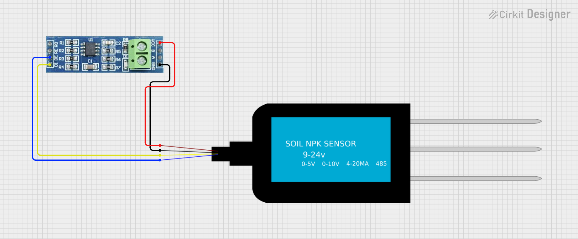 Open Project in Cirkit Designer
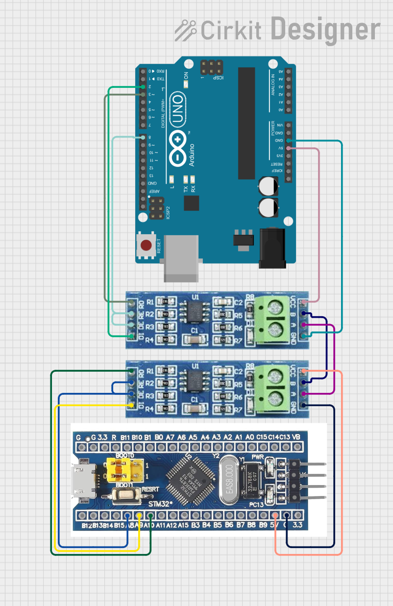 Open Project in Cirkit Designer
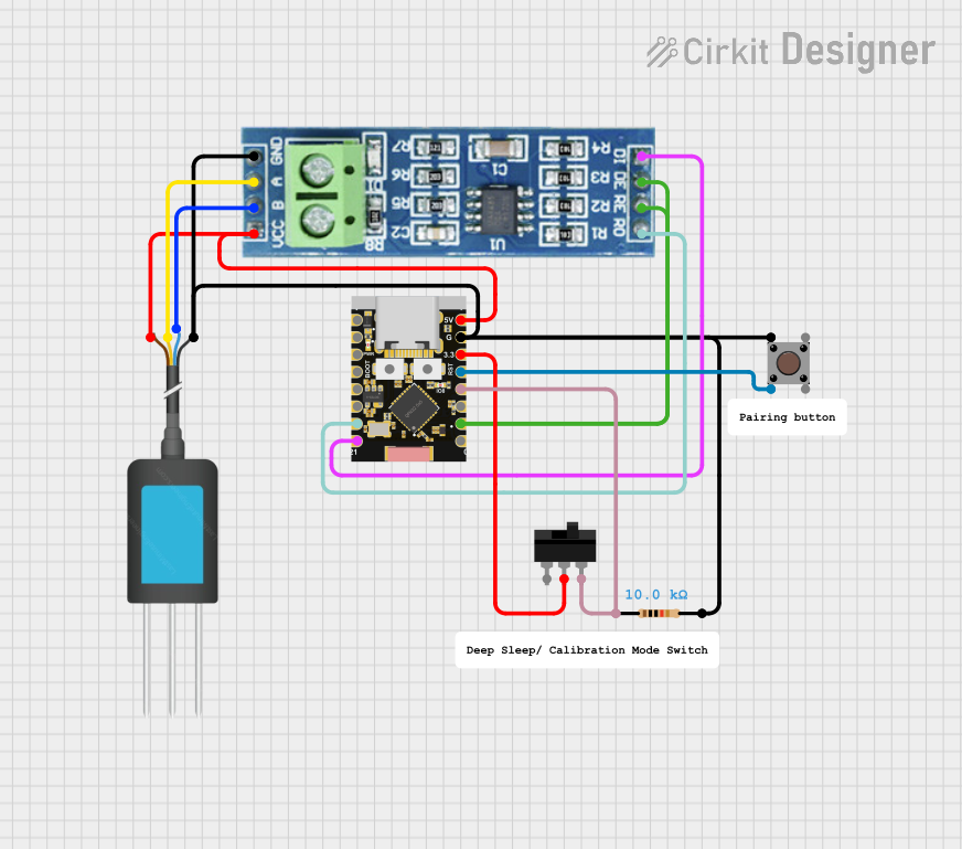 Open Project in Cirkit Designer
Explore Projects Built with TTL TO 485
Open Project in Cirkit DesignerOpen Project in Cirkit DesignerOpen Project in Cirkit DesignerOpen Project in Cirkit DesignerCommon Applications and Use Cases
- Industrial automation and control systems
- Long-distance communication between microcontrollers
- Interfacing sensors or devices with RS-485 networks
- Home automation and building management systems
- Data acquisition systems
Technical Specifications
The TTL to RS-485 converter is built to ensure reliable communication and compatibility with a wide range of devices. Below are the key technical details:
General Specifications
| Parameter | Value |
|---|---|
| Communication Protocol | RS-485 |
| TTL Voltage Levels | 3.3V or 5V (selectable) |
| RS-485 Voltage Levels | Differential signaling (-7V to +12V) |
| Baud Rate Support | Up to 115200 bps |
| Operating Voltage | 3.3V or 5V |
| Power Consumption | Low power (<50 mA) |
| Operating Temperature | -40°C to +85°C |
| Dimensions | Compact module (varies by model) |
Pin Configuration and Descriptions
| Pin Name | Direction | Description |
|---|---|---|
| VCC | Input | Power supply input (3.3V or 5V) |
| GND | Input | Ground connection |
| TXD | Input | TTL transmit data (from microcontroller) |
| RXD | Output | TTL receive data (to microcontroller) |
| A (D+) | Output | RS-485 differential signal positive (non-inverting) |
| B (D-) | Output | RS-485 differential signal negative (inverting) |
| DE | Input | Driver enable (active high) |
| RE | Input | Receiver enable (active low) |
Usage Instructions
How to Use the Component in a Circuit
- Power the Module: Connect the
VCCpin to a 3.3V or 5V power source and theGNDpin to ground. - Connect TTL Signals:
- Connect the
TXDpin to the transmit pin (e.g., TX) of your microcontroller. - Connect the
RXDpin to the receive pin (e.g., RX) of your microcontroller.
- Connect the
- RS-485 Network Connection:
- Connect the
A (D+)andB (D-)pins to the RS-485 network. - Ensure proper termination resistors (typically 120Ω) are used at both ends of the RS-485 bus.
- Connect the
- Enable Communication:
- Set the
DEpin high to enable the driver for transmitting data. - Set the
REpin low to enable the receiver for receiving data.
- Set the
Important Considerations and Best Practices
- Voltage Compatibility: Ensure the module's operating voltage matches your microcontroller's logic level (3.3V or 5V).
- Termination Resistors: Use 120Ω termination resistors at both ends of the RS-485 bus to prevent signal reflections.
- Biasing Resistors: Add pull-up and pull-down resistors on the RS-485 bus to maintain a known idle state.
- Cable Selection: Use twisted-pair cables for RS-485 connections to minimize noise and signal degradation.
- Distance Limitations: RS-485 supports communication over distances up to 1200 meters, but ensure proper wiring and signal integrity for long runs.
Example Code for Arduino UNO
Below is an example of how to use the TTL to RS-485 converter with an Arduino UNO for basic communication:
// Example: Sending data from Arduino UNO via TTL to RS-485 converter

#define DE_PIN 2  // Driver Enable pin connected to Arduino digital pin 2
#define RE_PIN 3  // Receiver Enable pin connected to Arduino digital pin 3

void setup() {
  Serial.begin(9600); // Initialize serial communication at 9600 baud
  pinMode(DE_PIN, OUTPUT); // Set DE pin as output
  pinMode(RE_PIN, OUTPUT); // Set RE pin as output

  digitalWrite(DE_PIN, LOW); // Disable driver initially
  digitalWrite(RE_PIN, LOW); // Enable receiver initially
}

void loop() {
  // Enable driver to send data
  digitalWrite(DE_PIN, HIGH); // Enable driver
  digitalWrite(RE_PIN, HIGH); // Disable receiver

  Serial.println("Hello, RS-485!"); // Send data via RS-485
  delay(1000); // Wait for 1 second

  // Switch back to receiving mode
  digitalWrite(DE_PIN, LOW); // Disable driver
  digitalWrite(RE_PIN, LOW); // Enable receiver
}
Troubleshooting and FAQs
Common Issues and Solutions
No Communication on RS-485 Bus:
- Verify the
DEandREpins are correctly set for transmitting or receiving. - Check the wiring of the
A (D+)andB (D-)pins to the RS-485 network. - Ensure proper termination resistors are in place.
- Verify the
Data Corruption or Noise:
- Use shielded twisted-pair cables for RS-485 connections.
- Add biasing resistors to maintain a stable idle state on the RS-485 bus.
Incorrect Voltage Levels:
- Confirm the module's operating voltage matches the microcontroller's logic level (3.3V or 5V).
Module Overheating:
- Check for short circuits or excessive current draw.
- Ensure the module is not exposed to temperatures beyond its operating range.
FAQs
Q: Can I use this module with a 3.3V microcontroller?
A: Yes, the module supports both 3.3V and 5V logic levels. Ensure the VCC pin is connected to the appropriate voltage.
Q: How many devices can I connect to the RS-485 bus?
A: RS-485 supports up to 32 devices on a single bus. For larger networks, use repeaters.
Q: Do I need to manually control the DE and RE pins?
A: Yes, you need to toggle these pins to switch between transmitting and receiving modes. Alternatively, some modules may include automatic flow control.
Q: What is the maximum communication distance?
A: RS-485 supports distances up to 1200 meters, but this depends on the baud rate and cable quality.