How to Use Rotary Potentiometer: Examples, Pinouts, and Specs
Introduction
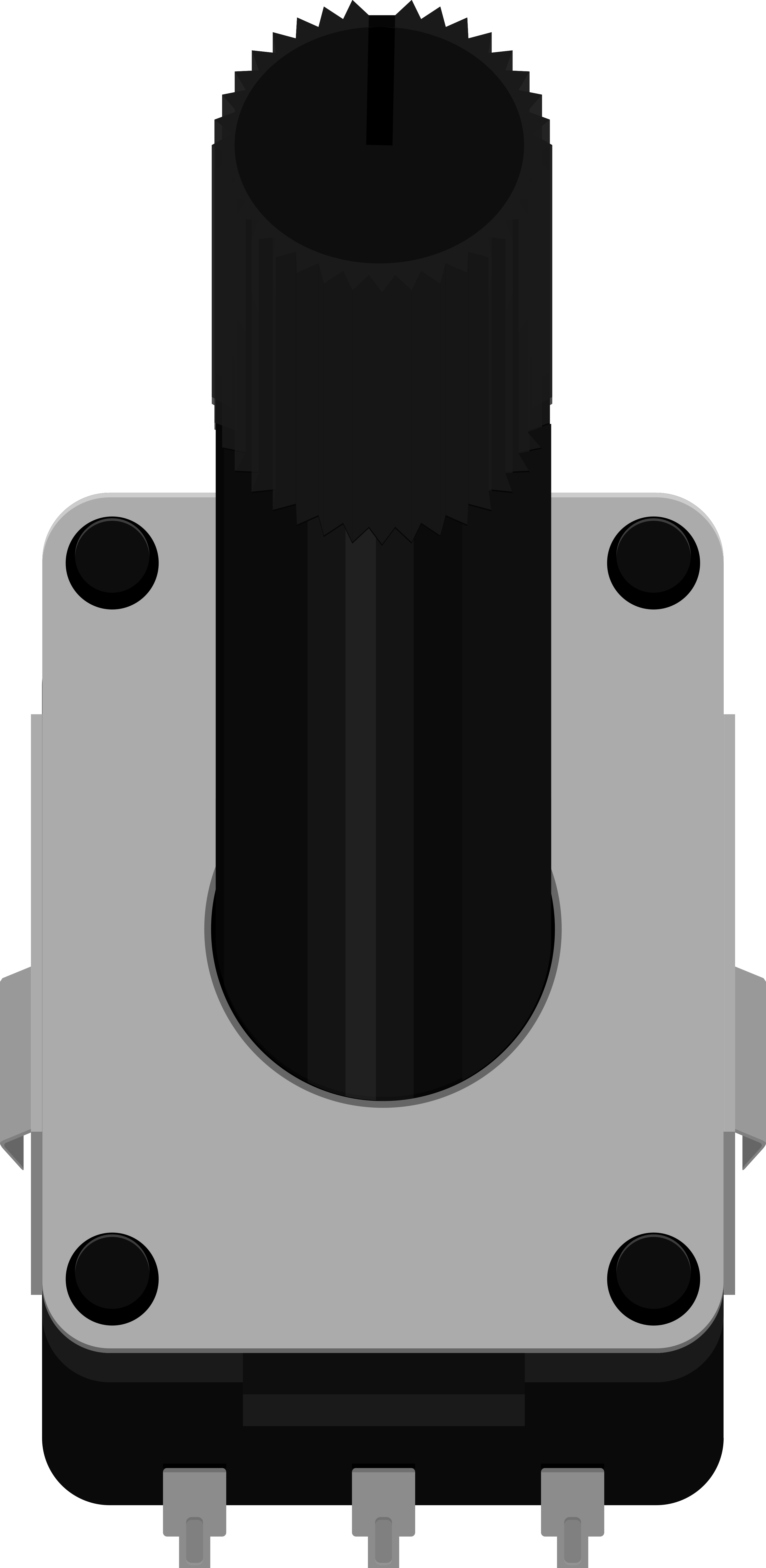
A rotary potentiometer, often referred to simply as a "pot," is a variable resistor with a knob or dial that can be turned to adjust resistance. It is a passive electronic component that provides a variable resistance, which can be used to control voltage or current in an electronic circuit. Rotary potentiometers are commonly used in applications such as volume control in audio equipment, as a control input for analog signals, and in various other applications where user input is needed to adjust a parameter.
Explore Projects Built with Rotary Potentiometer
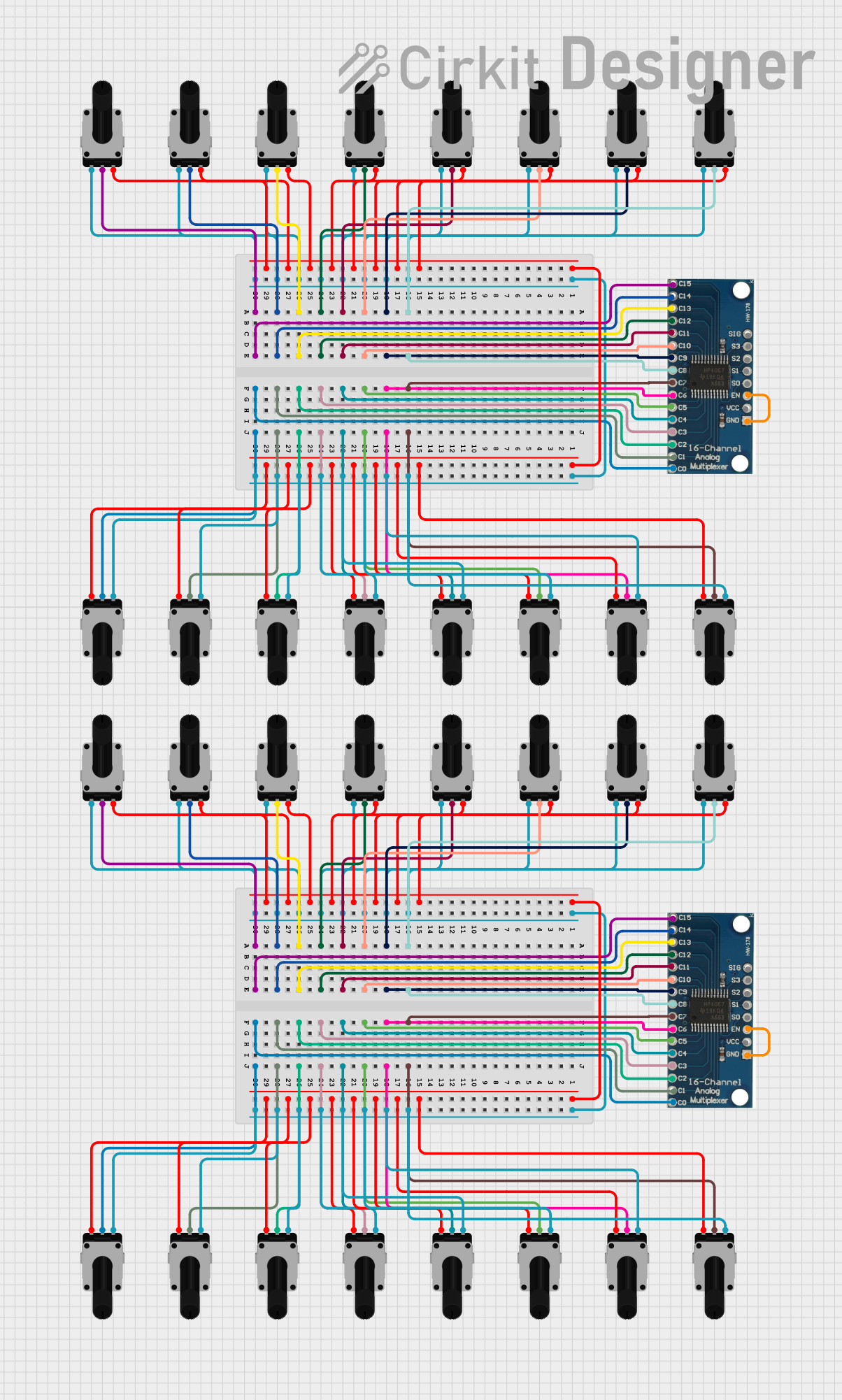


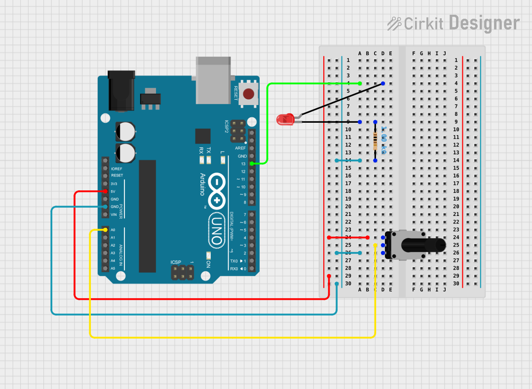
Explore Projects Built with Rotary Potentiometer
Technical Specifications
Key Technical Details
- Resistance Range: Typically from 1 kΩ to 1 MΩ
- Tolerance: ±10% to ±20% of nominal resistance
- Power Rating: Usually between 0.1W to 0.5W for standard potentiometers
- Voltage Rating: Maximum voltage depends on the specific model and manufacturer
- Temperature Coefficient: Varies with the material used for the resistive element
- Rotational Life: Number of cycles can range from 10,000 to 1,000,000 depending on the quality
Pin Configuration and Descriptions
| Pin Number | Description |
|---|---|
| 1 | Counter-clockwise terminal (CCW) |
| 2 | Wiper terminal (the adjustable output) |
| 3 | Clockwise terminal (CW) |
Usage Instructions
How to Use the Component in a Circuit
Connection: Connect the CCW terminal to the ground and the CW terminal to the supply voltage. The wiper terminal will provide a variable voltage output that ranges between the supply voltage and ground, depending on the position of the knob.
Adjustment: Turning the knob clockwise typically increases the resistance between the wiper and the CCW terminal, and decreases the resistance between the wiper and the CW terminal.
Reading Values: To read the analog value from a potentiometer using a microcontroller like an Arduino, connect the wiper to one of the analog input pins.
Important Considerations and Best Practices
- Voltage Rating: Do not exceed the voltage rating of the potentiometer to prevent damage.
- Power Rating: Ensure that the power dissipated by the potentiometer does not exceed its power rating.
- Mounting: Secure the potentiometer firmly to prevent movement that could affect readings.
- Cleaning: Use appropriate cleaners for potentiometers to avoid damage to the resistive track.
Example Code for Arduino UNO
// Define the pin connected to the potentiometer wiper
const int potPin = A0;

void setup() {
  // Initialize serial communication at 9600 bits per second:
  Serial.begin(9600);
}

void loop() {
  // Read the value from the potentiometer
  int potValue = analogRead(potPin);
  // Convert the reading to a voltage assuming a 5V supply
  float voltage = potValue * (5.0 / 1023.0);
  // Print out the value in volts
  Serial.println(voltage);
  // Delay for a bit to avoid spamming the serial output
  delay(250);
}
Troubleshooting and FAQs
Common Issues
- Inconsistent Output: If the potentiometer output is erratic, check for loose connections or a dirty track.
- No Variation in Output: Ensure that the potentiometer is not damaged and that the wiper is making good contact with the resistive element.
Solutions and Tips for Troubleshooting
- Cleaning: Use a contact cleaner specifically designed for potentiometers to clean the resistive track.
- Connections: Double-check all connections, including solder joints, for reliability.
- Testing: Use a multimeter to test the resistance across the terminals to ensure the potentiometer is functioning correctly.
FAQs
Q: Can I use a potentiometer to control the brightness of an LED? A: Yes, you can use a potentiometer to adjust the current through an LED, thereby controlling its brightness. However, ensure that the current does not exceed the LED's maximum rating.
Q: What happens if I reverse the connections to the CW and CCW terminals? A: Reversing these connections will simply reverse the direction in which the resistance increases or decreases when the knob is turned.
Q: How do I choose the right value of potentiometer for my application? A: Consider the voltage and current in your circuit, as well as the desired range of adjustment. Choose a potentiometer with a maximum resistance that allows for the required variation in your application.