How to Use RFID-RC522: Examples, Pinouts, and Specs
Introduction
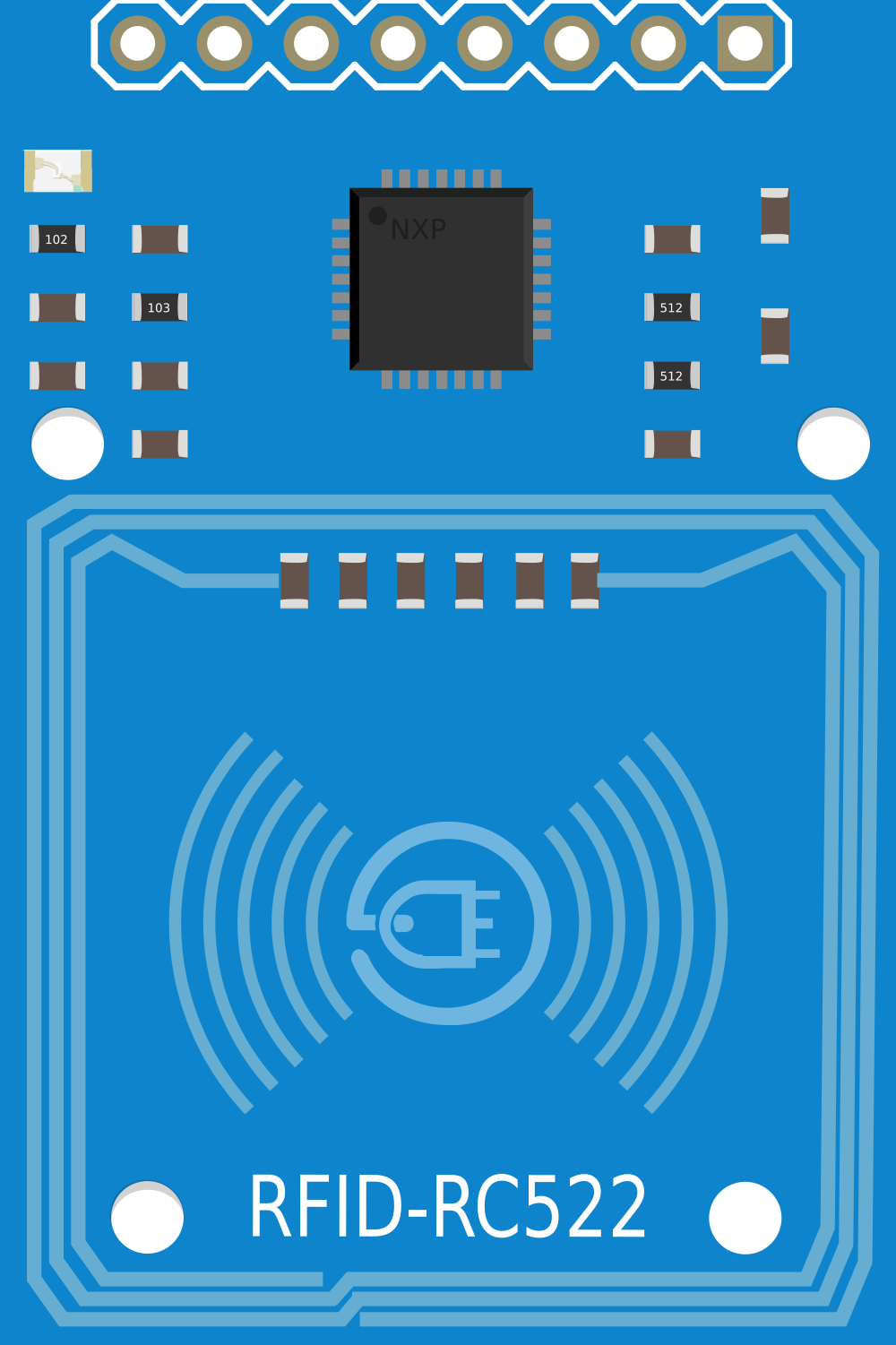
The RFID-RC522 is a highly integrated reader/writer module for contactless communication at 13.56 MHz. This module is based on the MFRC522 integrated circuit and is commonly used for RFID (Radio Frequency Identification) applications such as access control, attendance systems, and asset tracking. It supports ISO/IEC 14443A/MIFARE protocols, making it versatile for a wide range of RFID solutions.
Explore Projects Built with RFID-RC522
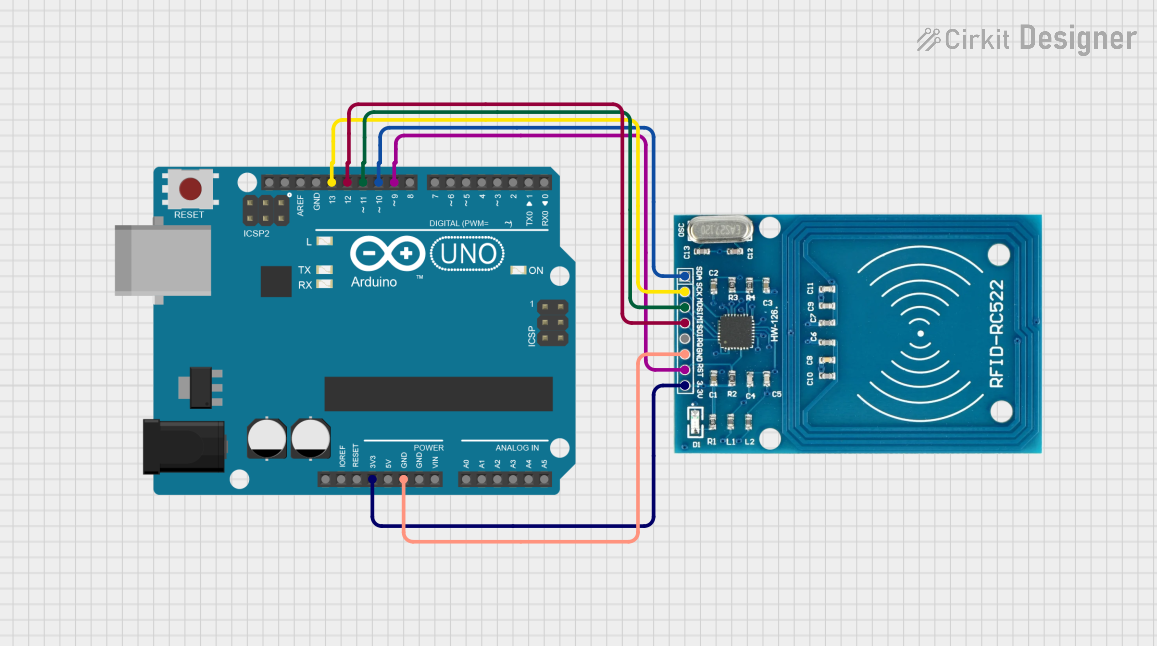
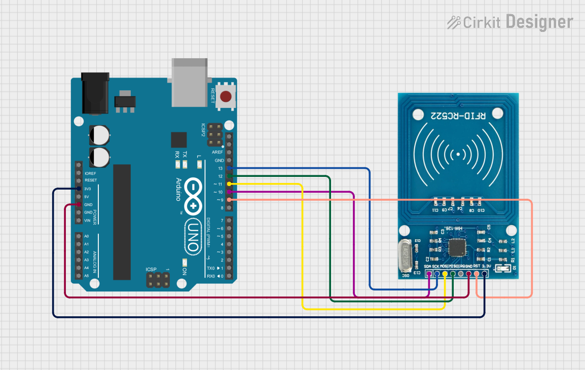
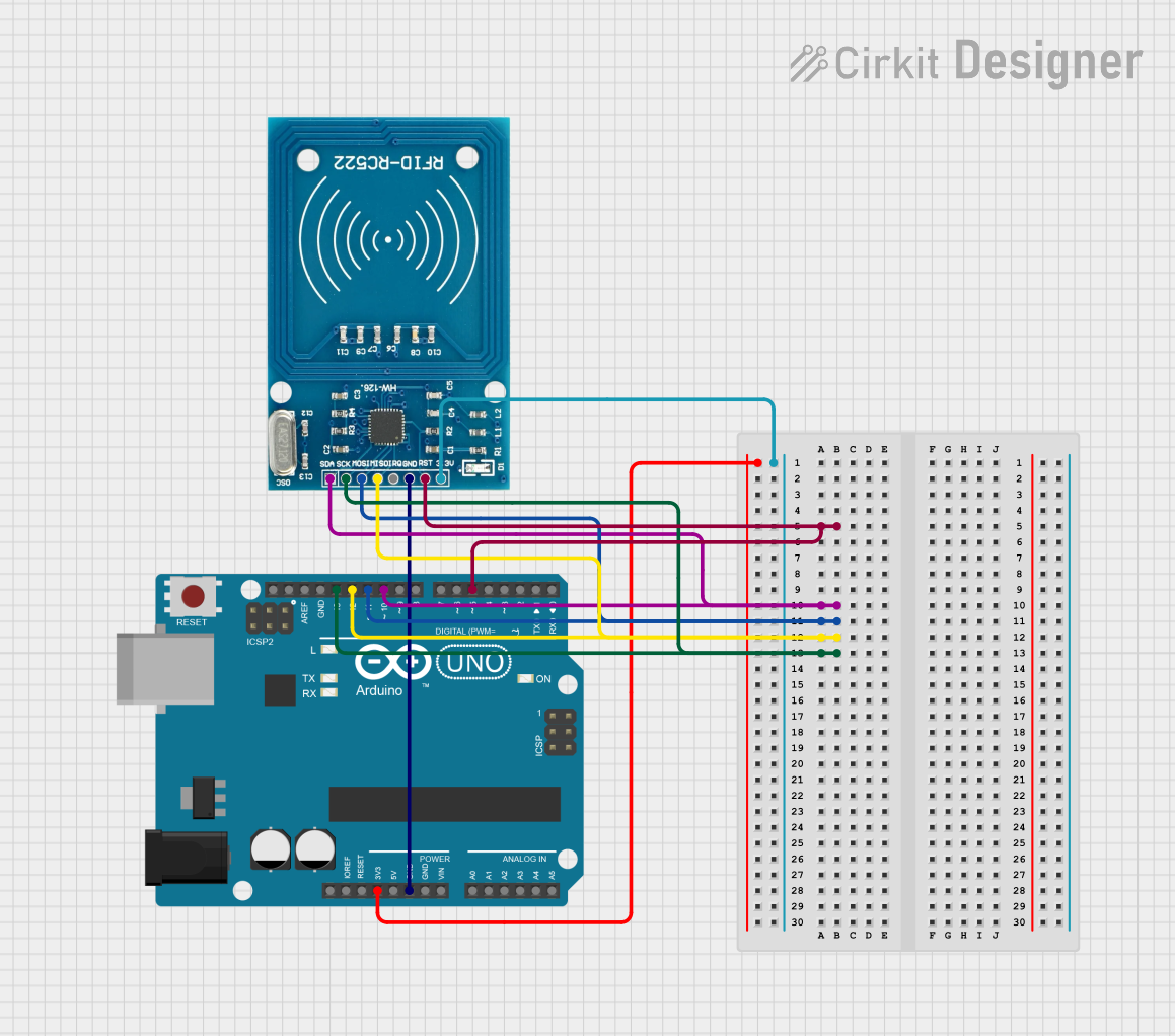
Explore Projects Built with RFID-RC522
Technical Specifications
Key Technical Details
- Operating Frequency: 13.56 MHz
- Supported Protocols: ISO/IEC 14443A/MIFARE
- Supply Voltage: 2.5V to 3.3V
- Current Consumption: 13-26 mA (operating); 10 uA (sleep)
- Operating Temperature Range: -20°C to +80°C
- Communication Interface: SPI
- Read Range: Up to 50 mm (depending on tag type and antenna geometry)
Pin Configuration and Descriptions
| Pin Name | Description |
|---|---|
| SDA | Serial Data Signal (SPI SS) |
| SCK | Serial Clock Signal (SPI SCK) |
| MOSI | Master Out Slave In (SPI MOSI) |
| MISO | Master In Slave Out (SPI MISO) |
| IRQ | Interrupt Request (optional use) |
| GND | Ground |
| RST | Reset Signal |
| 3.3V | Supply Voltage |
Usage Instructions
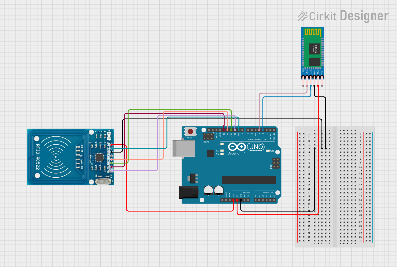
Integrating with a Circuit
To use the RFID-RC522 module in a circuit:
- Connect the module's power pins (3.3V and GND) to a 3.3V power supply.
- Interface the SPI pins (SDA, SCK, MOSI, MISO) with the microcontroller's corresponding SPI pins.
- Optionally, connect the RST pin to a digital pin on the microcontroller to control the reset function.
- The IRQ pin can be left unconnected if interrupt-driven operation is not required.
Best Practices
- Ensure that the power supply is stable and within the specified voltage range to prevent damage.
- Place the module away from metallic objects and electromagnetic interference to optimize the read range.
- Use proper decoupling capacitors close to the module's power pins to filter out noise.
- When designing the antenna layout, follow the guidelines provided in the MFRC522 datasheet for optimal performance.
Example Code for Arduino UNO
#include <SPI.h>
#include <MFRC522.h>

constexpr uint8_t RST_PIN = 9;  // Configurable, see typical pin layout above
constexpr uint8_t SS_PIN = 10;  // Configurable, see typical pin layout above

MFRC522 mfrc522(SS_PIN, RST_PIN);  // Create MFRC522 instance

void setup() {
  Serial.begin(9600); // Initialize serial communications with the PC
  SPI.begin();        // Init SPI bus
  mfrc522.PCD_Init(); // Init MFRC522 card
  Serial.println(F("Scan PICC to see UID and type..."));
}

void loop() {
  // Look for new cards
  if (!mfrc522.PICC_IsNewCardPresent() || !mfrc522.PICC_ReadCardSerial()) {
    delay(50);
    return;
  }

  // Show some details of the PICC (that is: the tag/card)
  Serial.print(F("Card UID:"));
  for (byte i = 0; i < mfrc522.uid.size; i++) {
    Serial.print(mfrc522.uid.uidByte[i] < 0x10 ? " 0" : " ");
    Serial.print(mfrc522.uid.uidByte[i], HEX);
  }
  Serial.println();
  // Additional card information can be included here

  // Halt PICC
  mfrc522.PICC_HaltA();
  // Stop encryption on PCD
  mfrc522.PCD_StopCrypto1();
}
Troubleshooting and FAQs
Common Issues
- Tag Read Failure: Ensure the tag is within the operational range and the antenna is not obstructed by metal surfaces.
- Communication Errors: Check the wiring and connections, and ensure that the SPI interface is correctly configured.
- Power Issues: Verify that the power supply is 3.3V and stable.
FAQs
Q: Can the RFID-RC522 module be used with a 5V system? A: The RFID-RC522 operates at 3.3V. A level shifter should be used when interfacing with a 5V system to avoid damaging the module.
Q: How can I increase the read range of the module? A: The read range can be affected by the antenna design, tag type, and environmental factors. Ensure optimal antenna design and placement, and use high-quality tags.
Q: What should I do if the module is not detecting any tags? A: Check the power supply, connections, and ensure that the SPI communication is functioning correctly. Also, verify that the tags are compatible and not damaged.
For further assistance, consult the MFRC522 datasheet and the manufacturer's resources.