How to Use A5984 Stepper Motor Driver Carrier: Examples, Pinouts, and Specs
Introduction
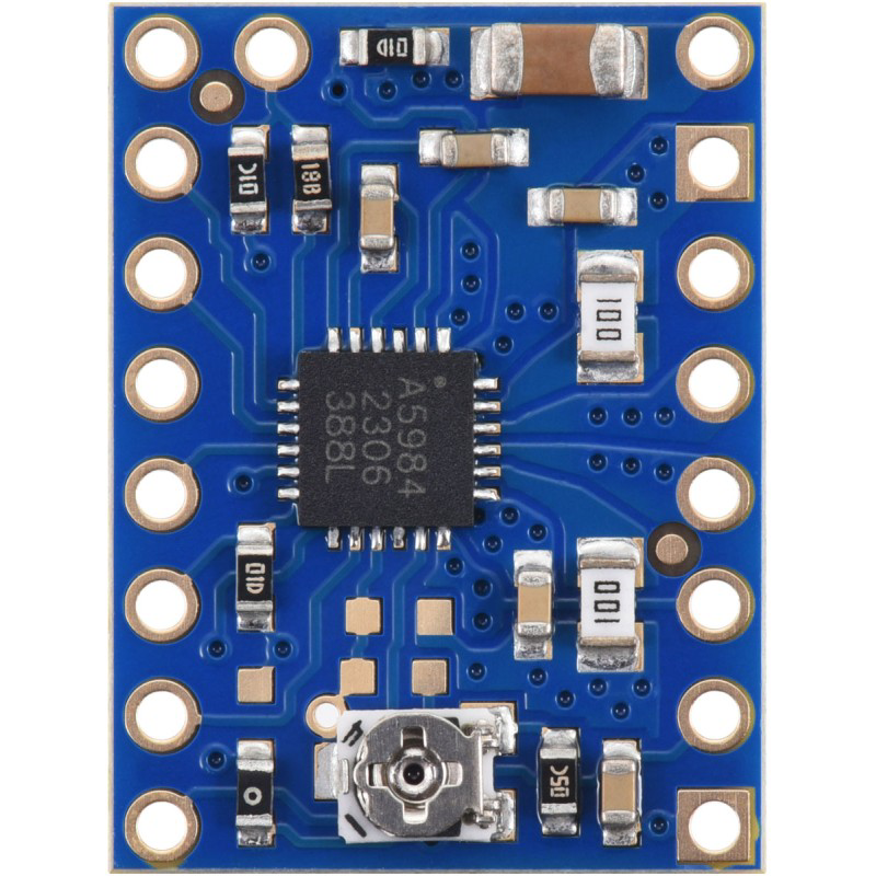
The A5984 Stepper Motor Driver Carrier by Pololu (Manufacturer Part ID: 1194453) is a compact and efficient driver designed to control bipolar stepper motors. It offers advanced features such as adjustable current control, microstepping capabilities (up to 1/32-step), and built-in protection mechanisms like overcurrent and thermal shutdown. This makes it an excellent choice for applications requiring precise motor control, such as robotics, 3D printers, CNC machines, and other automation systems.
Explore Projects Built with A5984 Stepper Motor Driver Carrier


Explore Projects Built with A5984 Stepper Motor Driver Carrier
Common Applications
- Robotics and mechatronics
- 3D printers and CNC machines
- Automated conveyor systems
- Camera gimbals and pan-tilt systems
- Precision positioning systems
Technical Specifications
Key Technical Details
| Parameter | Value |
|---|---|
| Operating Voltage (VMOT) | 8 V to 35 V |
| Logic Voltage (VDD) | 3.3 V or 5 V |
| Maximum Output Current | 1.5 A per phase (continuous) |
| Peak Output Current | 2.2 A per phase (with sufficient cooling) |
| Microstepping Modes | Full, 1/2, 1/4, 1/8, 1/16, 1/32 |
| Step Input Frequency | Up to 500 kHz |
| Built-in Protections | Overcurrent, thermal shutdown, undervoltage lockout |
| Dimensions | 0.6" × 0.8" × 0.1" (15 mm × 20 mm × 3 mm) |
| Weight | 1.2 g |
Pin Configuration and Descriptions
The A5984 Stepper Motor Driver Carrier has 16 pins. Below is the pinout and description:
| Pin Name | Type | Description |
|---|---|---|
| VMOT | Power Input | Motor power supply (8 V to 35 V). Connect a decoupling capacitor nearby. |
| GND | Power | Ground connection for motor and logic power supplies. |
| VDD | Power Input | Logic voltage supply (3.3 V or 5 V). |
| STEP | Input | Step signal input. Each pulse advances the motor by one step. |
| DIR | Input | Direction control input. High or low determines motor rotation direction. |
| MS1, MS2 | Input | Microstepping mode selection pins. See table below for configuration. |
| ENABLE | Input | Active-low enable pin. Pull low to enable the driver. |
| RESET | Input | Active-low reset pin. Pull low to reset internal logic. |
| SLEEP | Input | Active-low sleep pin. Pull low to minimize power consumption. |
| OUT1A, OUT1B | Output | Outputs for motor coil 1. |
| OUT2A, OUT2B | Output | Outputs for motor coil 2. |
| FAULT | Output | Open-drain fault indicator. Low when a fault condition occurs. |
| REF | Input | Reference voltage for current limit adjustment. |
Microstepping Mode Configuration
| MS1 | MS2 | Microstepping Mode |
|---|---|---|
| Low | Low | Full step |
| High | Low | Half step |
| Low | High | 1/4 step |
| High | High | 1/8, 1/16, or 1/32 step (default: 1/32) |
Usage Instructions
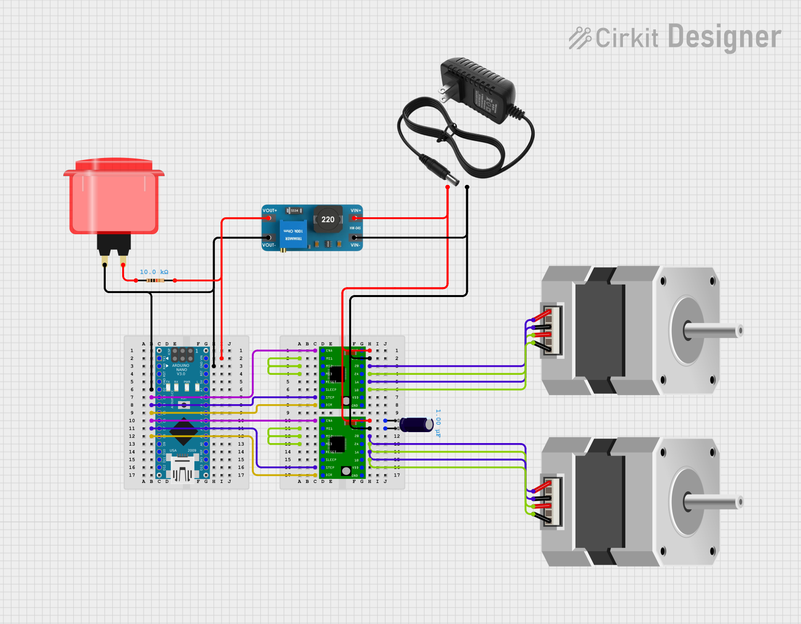
How to Use the A5984 in a Circuit
Power Connections:
- Connect the motor power supply (8 V to 35 V) to the
VMOTpin. - Connect the logic power supply (3.3 V or 5 V) to the
VDDpin. - Ensure all grounds (
GND) are connected.
- Connect the motor power supply (8 V to 35 V) to the
Motor Connections:
- Connect the two coils of the stepper motor to
OUT1A,OUT1B,OUT2A, andOUT2B. - Identify the motor coils using a multimeter if necessary.
- Connect the two coils of the stepper motor to
Control Signals:
- Use the
STEPpin to send pulses for stepping the motor. - Use the
DIRpin to set the rotation direction. - Configure the microstepping mode using the
MS1andMS2pins.
- Use the
Current Limiting:
- Adjust the current limit by setting the
REFvoltage. Use the formula:
whereCurrent Limit (A) = VREF / (8 × RS)RSis the sense resistor value (typically 0.1 Ω).
- Adjust the current limit by setting the
Enable and Sleep:
- Pull the
ENABLEpin low to activate the driver. - Pull the
SLEEPpin low to minimize power consumption when the driver is idle.
- Pull the
Example Arduino Code
Below is an example of how to control the A5984 Stepper Motor Driver Carrier with an Arduino UNO:
// Define pin connections
#define STEP_PIN 3  // Connect to STEP pin on A5984
#define DIR_PIN 4   // Connect to DIR pin on A5984
#define ENABLE_PIN 5 // Connect to ENABLE pin on A5984

void setup() {
  // Set pin modes
  pinMode(STEP_PIN, OUTPUT);
  pinMode(DIR_PIN, OUTPUT);
  pinMode(ENABLE_PIN, OUTPUT);

  // Enable the driver
  digitalWrite(ENABLE_PIN, LOW); // Pull ENABLE low to activate driver
}

void loop() {
  // Set direction
  digitalWrite(DIR_PIN, HIGH); // Set direction to clockwise

  // Step the motor
  for (int i = 0; i < 200; i++) { // 200 steps for one revolution (1.8°/step motor)
    digitalWrite(STEP_PIN, HIGH); // Generate a step pulse
    delayMicroseconds(1000);      // 1 ms pulse width
    digitalWrite(STEP_PIN, LOW);
    delayMicroseconds(1000);      // 1 ms delay between steps
  }

  delay(1000); // Wait 1 second before reversing direction

  // Reverse direction
  digitalWrite(DIR_PIN, LOW); // Set direction to counterclockwise

  // Step the motor in reverse
  for (int i = 0; i < 200; i++) {
    digitalWrite(STEP_PIN, HIGH);
    delayMicroseconds(1000);
    digitalWrite(STEP_PIN, LOW);
    delayMicroseconds(1000);
  }

  delay(1000); // Wait 1 second before repeating
}
Important Considerations
- Always use a decoupling capacitor (e.g., 100 µF) near the
VMOTpin to stabilize the motor power supply. - Ensure proper heat dissipation if operating near the maximum current limit.
- Avoid connecting or disconnecting the motor while the driver is powered to prevent damage.
Troubleshooting and FAQs
Common Issues and Solutions
Motor Not Moving:
- Verify power supply connections to
VMOTandVDD. - Check the
ENABLEpin is pulled low to activate the driver. - Ensure the
STEPpin is receiving pulses.
- Verify power supply connections to
Motor Vibrates but Does Not Rotate:
- Check the wiring of the motor coils. Ensure each coil is connected to the correct output pins.
- Verify the
DIRpin is set correctly for the desired direction.
Driver Overheating:
- Reduce the current limit by adjusting the
REFvoltage. - Add a heatsink or improve ventilation around the driver.
- Reduce the current limit by adjusting the
FAULT Pin is Low:
- Check for overcurrent or thermal shutdown conditions.
- Ensure the motor is not drawing more current than the driver can handle.
FAQs
Can I use the A5984 with a unipolar stepper motor? No, the A5984 is designed for bipolar stepper motors only.
What happens if I exceed the maximum input voltage? Exceeding 35 V on the
VMOTpin can permanently damage the driver. Use a regulated power supply.How do I select a microstepping mode? Set the
MS1andMS2pins according to the microstepping mode table provided in the technical specifications.
This concludes the documentation for the A5984 Stepper Motor Driver Carrier. For further assistance, refer to the Pololu product page or contact technical support.