Cirkit Designer Logo
Cirkit Designer
Your all-in-one circuit design IDE
Home / 
Component Documentation

How to Use LR7843 MODULE: Examples, Pinouts, and Specs

Image of LR7843 MODULE
Cirkit Designer LogoDesign with LR7843 MODULE in Cirkit Designer

Introduction

The LR7843 module is a low-power, high-performance wireless communication module designed for Internet of Things (IoT) applications. It supports various communication protocols, making it a versatile choice for connecting devices to the internet or other networks. Its compact design and energy efficiency make it ideal for battery-powered devices and embedded systems.

Explore Projects Built with LR7843 MODULE

Use Cirkit Designer to design, explore, and prototype these projects online. Some projects support real-time simulation. Click "Open Project" to start designing instantly!
Cellular-Enabled IoT Device with Real-Time Clock and Power Management
Image of LRCM PHASE 2 BASIC: A project utilizing LR7843 MODULE in a practical application
This circuit features a LilyGo-SIM7000G module for cellular communication and GPS functionality, interfaced with an RTC DS3231 for real-time clock capabilities. It includes voltage sensing through two voltage sensor modules, and uses an 8-channel opto-coupler for isolating different parts of the circuit. Power management is handled by a buck converter connected to a DC power source and batteries, with a fuse for protection and a rocker switch for on/off control. Additionally, there's an LED for indication purposes.
Cirkit Designer LogoOpen Project in Cirkit Designer
NFC-Enabled Access Control System with Time Logging
Image of doorlock: A project utilizing LR7843 MODULE in a practical application
This circuit is designed for access control with time tracking capabilities. It features an NFC/RFID reader for authentication, an RTC module (DS3231) for real-time clock functionality, and an OLED display for user interaction. A 12V relay controls a magnetic lock, which is activated upon successful NFC/RFID authentication, and a button switch is likely used for manual operation or input. The T8_S3 microcontroller serves as the central processing unit, interfacing with the NFC/RFID reader, RTC, OLED, and relay to manage the access control logic.
Cirkit Designer LogoOpen Project in Cirkit Designer
ESP32-Based Smart Access Control System with RFID, LCD Display, and Thermal Printer
Image of SCHEMATIC: A project utilizing LR7843 MODULE in a practical application
This circuit is an ESP32-based system that integrates multiple peripherals including an RFID reader, a relay module, a thermal printer, an I2C LCD screen, and a micro SD card module. The ESP32 controls the relay, reads RFID tags, prints data, displays information on the LCD, and logs data to the SD card, making it suitable for applications like access control or data logging systems.
Cirkit Designer LogoOpen Project in Cirkit Designer
Cellular-Connected ESP32-CAM with Real-Time Clock and Isolated Control
Image of LRCM PHASE 2 PRO: A project utilizing LR7843 MODULE in a practical application
This circuit integrates a LilyGo-SIM7000G module with an RTC DS3231 for timekeeping, interfaced via I2C (SCL and SDA lines). An 8-Channel OPTO-COUPLER is used to isolate and interface external signals with the LilyGo-SIM7000G's GPIOs. Power is managed by a Buck converter, which steps down voltage from a DC Power Source to supply the ESP32-CAM and LilyGo-SIM7000G modules, as well as the OPTO-COUPLER.
Cirkit Designer LogoOpen Project in Cirkit Designer

Explore Projects Built with LR7843 MODULE

Use Cirkit Designer to design, explore, and prototype these projects online. Some projects support real-time simulation. Click "Open Project" to start designing instantly!
Image of LRCM PHASE 2 BASIC: A project utilizing LR7843 MODULE in a practical application
Cellular-Enabled IoT Device with Real-Time Clock and Power Management
This circuit features a LilyGo-SIM7000G module for cellular communication and GPS functionality, interfaced with an RTC DS3231 for real-time clock capabilities. It includes voltage sensing through two voltage sensor modules, and uses an 8-channel opto-coupler for isolating different parts of the circuit. Power management is handled by a buck converter connected to a DC power source and batteries, with a fuse for protection and a rocker switch for on/off control. Additionally, there's an LED for indication purposes.
Cirkit Designer LogoOpen Project in Cirkit Designer
Image of doorlock: A project utilizing LR7843 MODULE in a practical application
NFC-Enabled Access Control System with Time Logging
This circuit is designed for access control with time tracking capabilities. It features an NFC/RFID reader for authentication, an RTC module (DS3231) for real-time clock functionality, and an OLED display for user interaction. A 12V relay controls a magnetic lock, which is activated upon successful NFC/RFID authentication, and a button switch is likely used for manual operation or input. The T8_S3 microcontroller serves as the central processing unit, interfacing with the NFC/RFID reader, RTC, OLED, and relay to manage the access control logic.
Cirkit Designer LogoOpen Project in Cirkit Designer
Image of SCHEMATIC: A project utilizing LR7843 MODULE in a practical application
ESP32-Based Smart Access Control System with RFID, LCD Display, and Thermal Printer
This circuit is an ESP32-based system that integrates multiple peripherals including an RFID reader, a relay module, a thermal printer, an I2C LCD screen, and a micro SD card module. The ESP32 controls the relay, reads RFID tags, prints data, displays information on the LCD, and logs data to the SD card, making it suitable for applications like access control or data logging systems.
Cirkit Designer LogoOpen Project in Cirkit Designer
Image of LRCM PHASE 2 PRO: A project utilizing LR7843 MODULE in a practical application
Cellular-Connected ESP32-CAM with Real-Time Clock and Isolated Control
This circuit integrates a LilyGo-SIM7000G module with an RTC DS3231 for timekeeping, interfaced via I2C (SCL and SDA lines). An 8-Channel OPTO-COUPLER is used to isolate and interface external signals with the LilyGo-SIM7000G's GPIOs. Power is managed by a Buck converter, which steps down voltage from a DC Power Source to supply the ESP32-CAM and LilyGo-SIM7000G modules, as well as the OPTO-COUPLER.
Cirkit Designer LogoOpen Project in Cirkit Designer

Common Applications and Use Cases

  • Smart home devices (e.g., smart thermostats, lighting systems)
  • Industrial IoT (e.g., remote monitoring, predictive maintenance)
  • Wearable technology
  • Wireless sensor networks
  • Asset tracking and fleet management
  • Environmental monitoring systems

Technical Specifications

The LR7843 module is designed to deliver reliable wireless communication while maintaining low power consumption. Below are its key technical details:

General Specifications

Parameter Value
Operating Voltage 3.3V
Operating Current 50mA (typical)
Communication Protocols Wi-Fi, Bluetooth, Zigbee
Frequency Range 2.4 GHz
Data Rate Up to 1 Mbps
Operating Temperature -40°C to +85°C
Dimensions 25mm x 15mm x 3mm

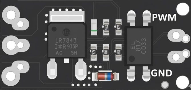
Pin Configuration and Descriptions

The LR7843 module typically has a 10-pin interface. Below is the pinout and description:

Pin Number Pin Name Description
1 VCC Power supply input (3.3V)
2 GND Ground
3 TX UART Transmit pin
4 RX UART Receive pin
5 EN Enable pin (active high)
6 GPIO1 General-purpose I/O pin
7 GPIO2 General-purpose I/O pin
8 RESET Reset pin (active low)
9 ANT Antenna connection
10 NC Not connected (reserved for future use)

Usage Instructions

The LR7843 module is straightforward to integrate into IoT projects. Below are the steps and best practices for using the module:

How to Use the LR7843 Module in a Circuit

  1. Power Supply: Connect the VCC pin to a stable 3.3V power source and the GND pin to the ground.
  2. Communication Interface: Use the TX and RX pins to establish UART communication with a microcontroller or other host device.
  3. Enable the Module: Pull the EN pin high to activate the module.
  4. Antenna Connection: Attach an appropriate antenna to the ANT pin for optimal wireless performance.
  5. Reset: Use the RESET pin to restart the module if needed.

Important Considerations and Best Practices

  • Voltage Levels: Ensure that the module operates at 3.3V. Using higher voltages may damage the module.
  • Antenna Placement: Place the antenna away from metal surfaces or other components to avoid signal interference.
  • UART Configuration: Configure the UART interface with the correct baud rate (typically 9600 bps) for reliable communication.
  • Firmware Updates: Check for firmware updates from the manufacturer to ensure compatibility with the latest protocols and features.

Example: Connecting the LR7843 Module to an Arduino UNO

Below is an example of how to connect and use the LR7843 module with an Arduino UNO:
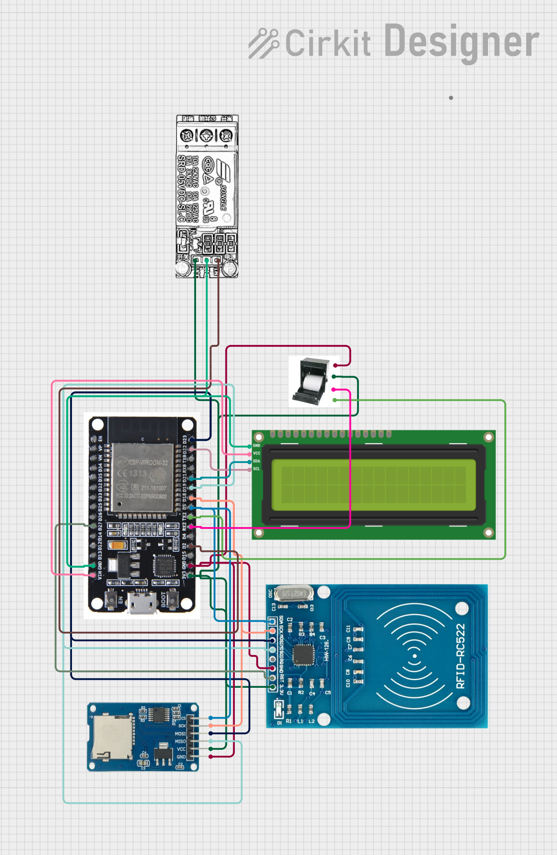
Wiring Diagram

LR7843 Pin Arduino Pin
VCC 3.3V
GND GND
TX Pin 10 (RX)
RX Pin 11 (TX)
EN 3.3V
RESET Pin 12

Arduino Code Example

#include <SoftwareSerial.h>

// Define RX and TX pins for SoftwareSerial
SoftwareSerial LR7843(10, 11); // RX = Pin 10, TX = Pin 11

void setup() {
  // Initialize serial communication with the module
  LR7843.begin(9600); // Set baud rate to 9600
  Serial.begin(9600); // For debugging via Serial Monitor

  // Enable the module
  pinMode(12, OUTPUT); // Set RESET pin as output
  digitalWrite(12, HIGH); // Pull RESET pin high to enable the module

  Serial.println("LR7843 Module Initialized");
}

void loop() {
  // Send data to the LR7843 module
  LR7843.println("Hello, LR7843!");

  // Check for incoming data from the module
  if (LR7843.available()) {
    String data = LR7843.readString();
    Serial.println("Received from LR7843: " + data);
  }

  delay(1000); // Wait for 1 second
}

Troubleshooting and FAQs

Common Issues and Solutions

  1. No Communication with the Module

    • Cause: Incorrect UART configuration or wiring.
    • Solution: Verify the TX and RX connections. Ensure the baud rate matches the module's default setting (9600 bps).
  2. Module Not Powering On

    • Cause: Insufficient or unstable power supply.
    • Solution: Ensure the VCC pin is connected to a stable 3.3V source. Check for loose connections.
  3. Weak or No Signal

    • Cause: Poor antenna placement or interference.
    • Solution: Reposition the antenna away from metal objects or other electronic components.
  4. Module Not Responding to Commands

    • Cause: Module not enabled or in reset state.
    • Solution: Ensure the EN pin is pulled high and the RESET pin is not held low.

FAQs

Q1: Can the LR7843 module operate at 5V?
A1: No, the module is designed to operate at 3.3V. Using 5V may damage the module.

Q2: What is the maximum range of the LR7843 module?
A2: The range depends on the communication protocol and environmental conditions. Typically, it can achieve up to 100 meters in open spaces.

Q3: Can I use the LR7843 module with other microcontrollers besides Arduino?
A3: Yes, the module can be used with any microcontroller that supports UART communication.

Q4: How do I update the firmware of the LR7843 module?
A4: Refer to the manufacturer's documentation for firmware update instructions. Typically, updates are performed via the UART interface.

By following this documentation, you can effectively integrate the LR7843 module into your IoT projects and troubleshoot common issues.