How to Use 74HC595: Examples, Pinouts, and Specs

Introduction
The 74HC595 is an 8-bit serial-in, parallel-out shift register with a storage register and 3-state outputs. It is part of the 74XX series of integrated circuits and is widely used in digital electronics for expanding the number of outputs using fewer pins from a microcontroller, such as an Arduino. This component is particularly useful for controlling multiple LEDs, display segments, or other digital output devices.
Explore Projects Built with 74HC595

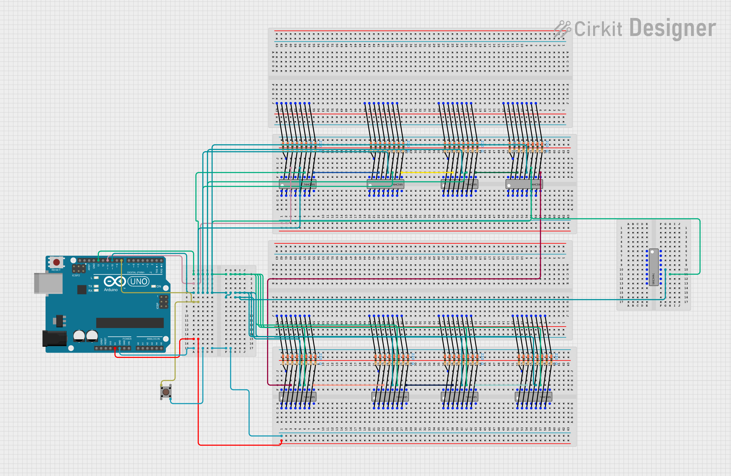
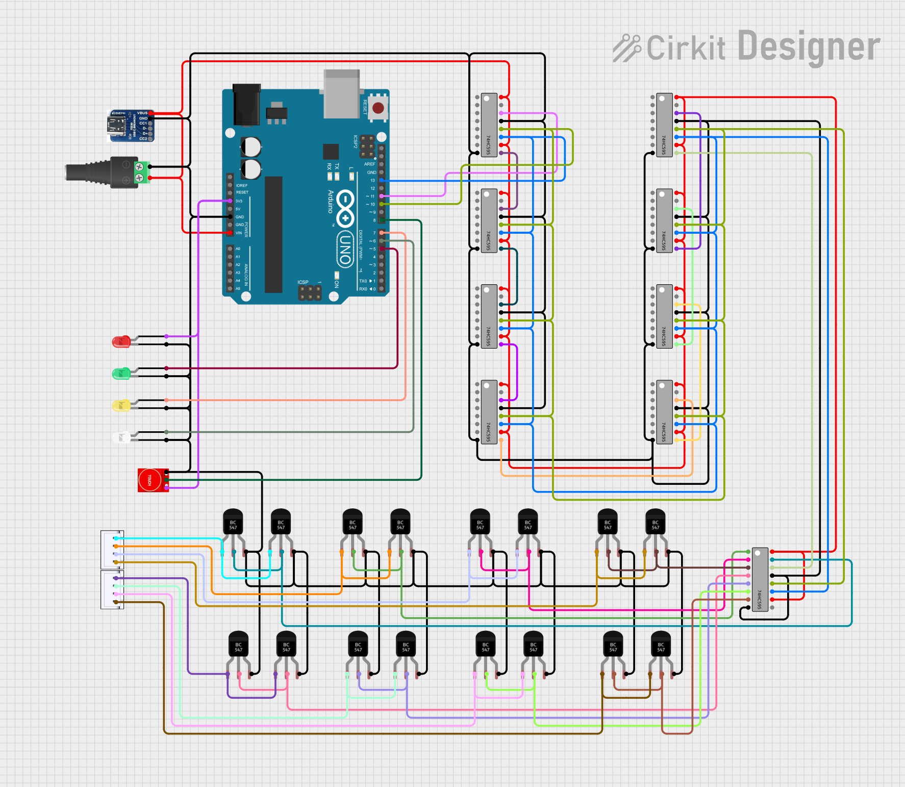
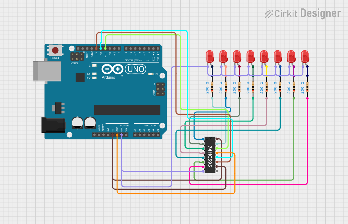
Explore Projects Built with 74HC595
Common Applications and Use Cases
- LED displays and matrix control
- Digital control of multiple outputs
- Serial to parallel data conversion
- Expanding I/O ports of microcontrollers
Technical Specifications
Key Technical Details
- Supply Voltage (Vcc): 2.0V to 6.0V
- Input Voltage (Vi): -0.5V to Vcc + 0.5V
- Output Voltage (Vo): -0.5V to Vcc + 0.5V
- Clock Frequency (fmax): 100MHz (typical at Vcc = 5V)
- Output Current (Io): ±35 mA
Pin Configuration and Descriptions
| Pin Number | Name | Description |
|---|---|---|
| 1 | Q1 | Serial Data Output |
| 2 | Q2 | Serial Data Output |
| 3 | Q3 | Serial Data Output |
| 4 | Q4 | Serial Data Output |
| 5 | Q5 | Serial Data Output |
| 6 | Q6 | Serial Data Output |
| 7 | Q7 | Serial Data Output |
| 8 | GND | Ground (0V) |
| 9 | Q7' | Serial Data Output for daisy-chaining |
| 10 | SRCLR | Shift Register Clear (Active Low) |
| 11 | SRCLK | Shift Register Clock Input |
| 12 | RCLK | Storage Register Clock Input |
| 13 | OE | Output Enable (Active Low) |
| 14 | SER | Serial Data Input |
| 15 | Q0 | Serial Data Output |
| 16 | Vcc | Positive Supply Voltage |
Usage Instructions
How to Use the Component in a Circuit
- Connect Vcc to a 2.0V to 6.0V power supply and GND to the ground.
- Connect the SER pin to the microcontroller's data output pin.
- Connect the SRCLK pin to the microcontroller's clock output pin.
- Connect the RCLK pin to the microcontroller's latch clock output pin.
- Optionally, connect the OE pin to ground to enable the outputs or to a microcontroller pin for output control.
- Connect the SRCLR pin to Vcc to prevent clearing the shift register.
- Connect the Q0-Q7 outputs to the devices you wish to control.
Important Considerations and Best Practices
- Ensure that the power supply voltage does not exceed the maximum Vcc rating.
- Use a current-limiting resistor with LEDs to prevent exceeding the maximum output current.
- To prevent data corruption, avoid changing the input data (SER) while the shift register clock (SRCLK) is high.
- When daisy-chaining multiple 74HC595s, connect the Q7' output of one to the SER input of the next.
Example Code for Arduino UNO
// Define the connections to the Arduino
const int dataPin = 2;    // SER to Arduino pin 2
const int latchPin = 3;   // RCLK to Arduino pin 3
const int clockPin = 4;   // SRCLK to Arduino pin 4

void setup() {
  // Set pins to output mode
  pinMode(dataPin, OUTPUT);
  pinMode(latchPin, OUTPUT);
  pinMode(clockPin, OUTPUT);
}

void loop() {
  // Example: shift out the binary value '10101010'
  digitalWrite(latchPin, LOW); // Prepare to latch data
  shiftOut(dataPin, clockPin, MSBFIRST, 0b10101010);
  digitalWrite(latchPin, HIGH); // Latch data onto the outputs
  delay(1000); // Wait for a second
}
Troubleshooting and FAQs
Common Issues Users Might Face
- LEDs are not lighting up: Check the connections and ensure that the OE pin is connected to ground or properly controlled by the microcontroller.
- Incorrect outputs: Verify that the data is being latched at the correct time and that the SRCLR pin is held high unless a clear is intended.
- Daisy-chained 74HC595s not working correctly: Ensure that the Q7' of one shift register is correctly connected to the SER of the next and that the clock signals are properly synchronized.
Solutions and Tips for Troubleshooting
- Use a multimeter to check for correct voltages at the Vcc and GND pins.
- Ensure that the clock and latch signals are clean and free of noise.
- If using multiple 74HC595s, check the timing of the data and clock signals to ensure proper synchronization.
FAQs
Q: Can I drive high-power devices directly with the 74HC595? A: No, the 74HC595 can only source or sink a limited amount of current. Use a transistor or a driver IC for high-power applications.
Q: How many 74HC595s can I daisy-chain together? A: You can daisy-chain as many as you need, provided that the microcontroller can handle the timing and that the power supply can provide sufficient current for all connected devices.
Q: Is it necessary to use the OE pin? A: The OE pin is optional but useful for enabling or disabling the outputs without clearing the shift register. If not used, it should be tied to ground to enable the outputs.
Remember to follow all safety precautions when working with electronic components and ensure that all connections are secure before applying power to the circuit.