How to Use VFD-220V(1PH)-1.5KW: Examples, Pinouts, and Specs
Introduction
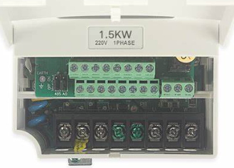
The VFD-220V(1PH)-1.5KW (Manufacturer Part ID: ZT-D12) is a Variable Frequency Drive (VFD) manufactured by SOWAKAM. It is designed to operate with a 220V single-phase input and is capable of controlling motors up to 1.5 kW. By varying the frequency and voltage supplied to the motor, this VFD enables precise control of motor speed and torque, making it an essential component in industrial automation, HVAC systems, and other motor-driven applications.
Explore Projects Built with VFD-220V(1PH)-1.5KW
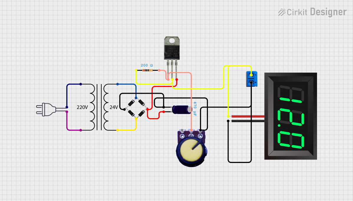


Explore Projects Built with VFD-220V(1PH)-1.5KW
Common Applications and Use Cases
- Industrial Automation: Conveyor belts, pumps, and fans.
- HVAC Systems: Controlling air handling units and compressors.
- Energy Efficiency: Reducing power consumption by optimizing motor speed.
- Agriculture: Irrigation systems and grain elevators.
- General Purpose Motor Control: Applications requiring variable speed and torque.
Technical Specifications
Key Technical Details
| Parameter | Specification |
|---|---|
| Input Voltage | 220V AC (Single-Phase) |
| Output Voltage | 0–220V AC (Three-Phase) |
| Output Frequency Range | 0.1–400 Hz |
| Maximum Motor Power | 1.5 kW |
| Control Mode | V/F Control, Open-Loop Vector |
| Overload Capacity | 150% of rated current for 1 minute |
| Operating Temperature | -10°C to 50°C |
| Protection Features | Overvoltage, Undervoltage, Overload, Short Circuit |
| Dimensions (L x W x H) | 150 mm x 100 mm x 200 mm |
| Weight | 1.8 kg |
Pin Configuration and Descriptions
The VFD has multiple input/output terminals for control and power connections. Below is the pin configuration:
Power Terminals
| Terminal Label | Description |
|---|---|
| L/N | Single-phase 220V AC input |
| U/V/W | Three-phase motor output |
| PE | Protective Earth (Ground) |
Control Terminals
| Terminal Label | Description |
|---|---|
| FWD | Forward Run Command Input |
| REV | Reverse Run Command Input |
| COM | Common Ground for Control Signals |
| AI | Analog Input (0–10V or 4–20mA) for Speed Control |
| AO | Analog Output (0–10V) for Monitoring |
| DI1–DI4 | Digital Inputs for Programmable Functions |
| DO | Digital Output for Fault or Status Indication |
Usage Instructions
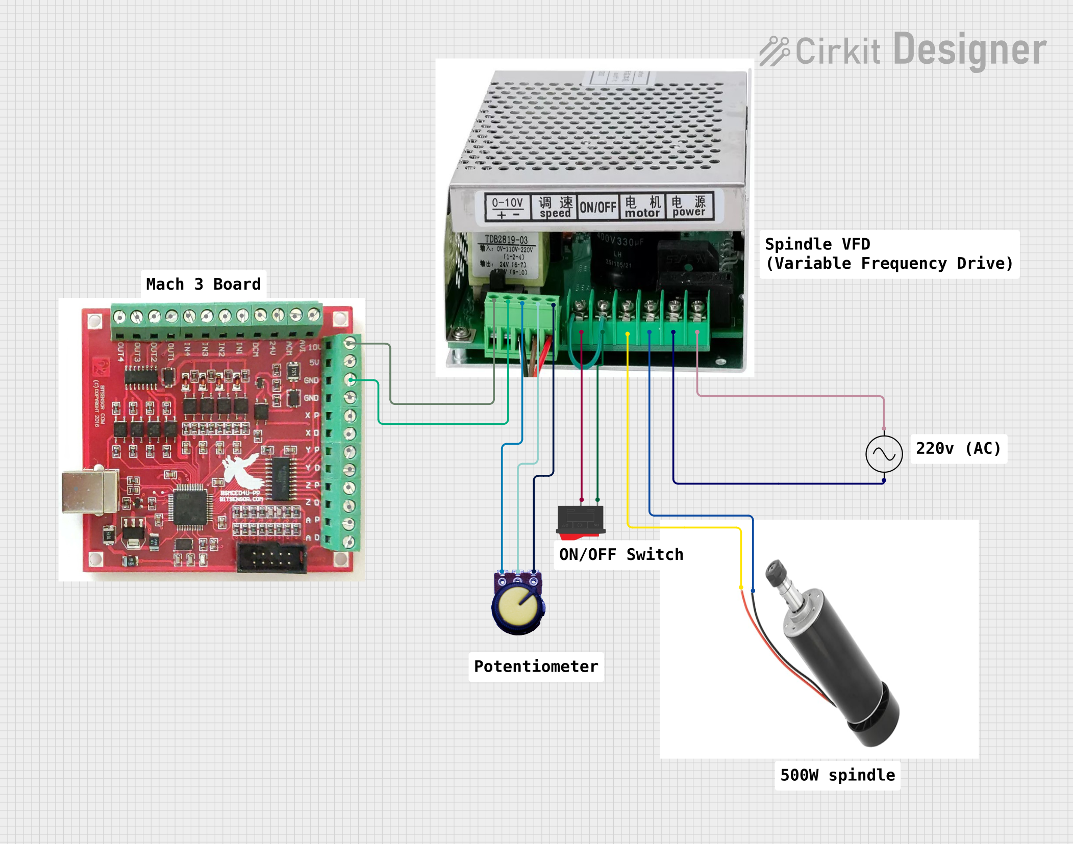
How to Use the Component in a Circuit
Power Connection:
- Connect the single-phase 220V AC input to the L and N terminals.
- Connect the motor's three-phase wires to the U, V, and W terminals.
- Ensure the PE terminal is properly grounded for safety.
Control Wiring:
- Use the FWD and REV terminals to control the motor's direction.
- For speed control, connect a potentiometer or analog signal (0–10V or 4–20mA) to the AI terminal.
- Configure the digital inputs (DI1–DI4) for additional control functions, such as start/stop or preset speeds.
Programming the VFD:
- Use the built-in keypad and display to configure parameters such as motor type, maximum frequency, and acceleration/deceleration times.
- Refer to the manufacturer's manual for detailed parameter settings.
Testing:
- After wiring and programming, test the VFD with the motor at low speed to ensure proper operation.
- Gradually increase the speed and monitor the motor's performance.
Important Considerations and Best Practices
- Cooling: Ensure adequate ventilation around the VFD to prevent overheating.
- Cable Shielding: Use shielded cables for motor connections to reduce electromagnetic interference (EMI).
- Overcurrent Protection: Install fuses or circuit breakers on the input side for added protection.
- Parameter Settings: Double-check all parameter settings before running the motor to avoid damage.
- Startup: Always start the motor at a low frequency and gradually increase to the desired speed.
Arduino UNO Integration Example
The VFD can be controlled using an Arduino UNO via the analog input (AI) terminal. Below is an example code to control the motor speed using a potentiometer connected to the Arduino.
// Arduino code to control VFD speed using a potentiometer
const int potPin = A0;  // Potentiometer connected to analog pin A0
const int vfdPin = 9;   // PWM output to VFD AI terminal

void setup() {
  pinMode(vfdPin, OUTPUT);  // Set VFD pin as output
}

void loop() {
  int potValue = analogRead(potPin);  // Read potentiometer value (0–1023)
  int pwmValue = map(potValue, 0, 1023, 0, 255);
  // Map pot value to PWM range (0–255)

  analogWrite(vfdPin, pwmValue);  // Output PWM signal to VFD
  delay(10);  // Small delay for stability
}
Note: Ensure the Arduino's PWM output is compatible with the VFD's analog input range (0–10V). A voltage level shifter may be required.
Troubleshooting and FAQs
Common Issues and Solutions
| Issue | Possible Cause | Solution |
|---|---|---|
| VFD does not power on | No input power or loose connections | Check input voltage and connections. |
| Motor does not start | Incorrect wiring or parameter settings | Verify wiring and recheck parameters. |
| Motor runs in the wrong direction | Phase sequence mismatch | Swap any two motor output wires. |
| Overload or overcurrent fault | Motor is overloaded or misconfigured | Reduce load or adjust parameters. |
| Excessive noise or vibration | EMI or improper grounding | Use shielded cables and check grounding. |
FAQs
Can this VFD be used with a single-phase motor?
- No, this VFD is designed for three-phase motors only.
What is the maximum cable length between the VFD and motor?
- The recommended maximum length is 50 meters. Use shielded cables for longer distances.
How do I reset the VFD to factory settings?
- Refer to the manufacturer's manual for the specific reset procedure, typically accessible via the keypad.
Can I use this VFD outdoors?
- No, the VFD must be installed in a dry, dust-free environment with adequate ventilation.
What happens if the input voltage exceeds 220V?
- The VFD has overvoltage protection, but prolonged overvoltage may damage the unit. Use a voltage stabilizer if necessary.
This documentation provides a comprehensive guide to the VFD-220V(1PH)-1.5KW. For further assistance, refer to the manufacturer's manual or contact SOWAKAM support.