How to Use Illuminated Rocker Switch: Examples, Pinouts, and Specs

Introduction
An Illuminated Rocker Switch is a user-friendly and intuitive electrical component that combines the functionality of a standard rocker switch with the added feature of an indicator light. This switch is designed to provide visual feedback, making it easy to determine whether a circuit is active at a glance. Commonly found in automotive dashboards, household appliances, and industrial control panels, the illuminated rocker switch is a versatile component suitable for a wide range of applications.
Explore Projects Built with Illuminated Rocker Switch

Explore Projects Built with Illuminated Rocker Switch
Technical Specifications
General Specifications
- Switch Type: SPST (Single Pole, Single Throw)
- Illumination: LED or Neon Lamp
- Voltage Rating: Typically 12VDC for LED, 120VAC for Neon
- Current Rating: Varies with model (e.g., 10A at 250VAC)
- Contact Resistance: <50mΩ initial
- Insulation Resistance: >100MΩ at 500VDC
- Dielectric Strength: >1500VAC for 1 minute
- Operating Temperature: -20°C to +85°C
- Electrical Life: >10,000 cycles
- Mechanical Life: >50,000 cycles
Pin Configuration and Descriptions
| Pin Number | Description |
|---|---|
| 1 | Input (Power Supply) |
| 2 | Output (Load) |
| 3 | Ground (for LED illumination) |
Note: The pin configuration may vary depending on the manufacturer. Always refer to the manufacturer's datasheet for exact specifications.
Usage Instructions
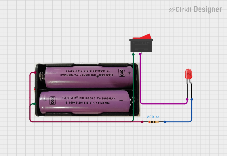
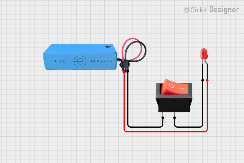
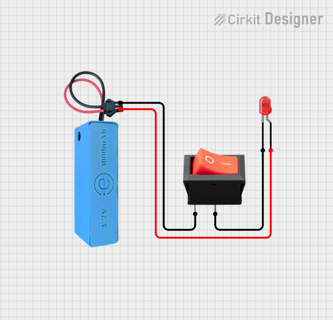
Wiring the Switch
- Power Supply Connection: Connect the power supply to Pin 1. This is where the voltage input for both the switch and the illumination is provided.
- Load Connection: Connect the load you wish to control to Pin 2. This is the output pin that will be toggled on and off by the switch.
- Ground Connection: Connect Pin 3 to the ground of your circuit. This is necessary for completing the circuit of the LED indicator.
Best Practices
- Ensure the voltage and current ratings of the switch match the requirements of your application.
- Use a current-limiting resistor if the built-in LED requires a lower voltage than the power supply.
- Avoid excessive force on the switch actuator to prevent mechanical damage.
- When mounting the switch, ensure a secure fit to prevent movement that could lead to wiring fatigue or failure.
Troubleshooting and FAQs
Q: The switch operates the load but the indicator light does not illuminate. What could be the problem?
A: Check the ground connection to Pin 3. If the ground is not properly connected, the indicator light will not function.
Q: Can I use the switch with a voltage different from the rated voltage?
A: Using the switch with a voltage higher than its rating can damage the component. If using a lower voltage, ensure that the indicator light is compatible with the lower voltage.
Q: The switch feels loose and does not maintain its position. What should I do?
A: Verify that the switch is properly mounted and that the terminals are not loose. If the issue persists, the switch may be mechanically worn out and require replacement.
Q: How can I test if the switch is functioning properly?
A: Use a multimeter to check for continuity between Pins 1 and 2 when the switch is in the 'on' position. There should be no continuity when the switch is 'off'.
For additional support, consult the manufacturer's datasheet or contact technical support.
Note: This documentation is for informational purposes only. Always follow the manufacturer's installation and safety guidelines.