
How to Use T8S 2.4G Transmitter: Examples, Pinouts, and Specs
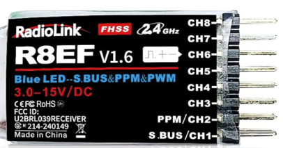
 Design with T8S 2.4G Transmitter in Cirkit Designer
Introduction
The T8S 2.4G Transmitter by RadioLink is a compact and versatile wireless transmitter designed for remote control applications. Operating in the 2.4 GHz frequency band, it ensures reliable and interference-resistant communication with compatible receivers. Its lightweight design and user-friendly interface make it ideal for controlling drones, RC cars, boats, and other remote-controlled devices.
Explore Projects Built with T8S 2.4G Transmitter
 Open Project in Cirkit Designer
 Open Project in Cirkit Designer
 Open Project in Cirkit Designer
 Open Project in Cirkit Designer
Explore Projects Built with T8S 2.4G Transmitter
Open Project in Cirkit DesignerOpen Project in Cirkit DesignerOpen Project in Cirkit DesignerOpen Project in Cirkit DesignerCommon Applications and Use Cases
- Remote control of drones and quadcopters
- RC cars, boats, and aircraft
- Robotics and automation systems
- Wireless communication for hobbyist projects
- Educational and prototyping purposes
Technical Specifications
The following table outlines the key technical details of the T8S 2.4G Transmitter:
| Specification | Details |
|---|---|
| Operating Frequency | 2.4 GHz |
| Modulation Type | DSSS (Direct Sequence Spread Spectrum) |
| Channels | 8 |
| Transmission Range | Up to 400 meters (line of sight) |
| Power Supply | 3.7V LiPo battery (not included) |
| Current Consumption | ≤ 100 mA |
| Dimensions | 159 mm x 97 mm x 50 mm |
| Weight | 210 g |
| Compatibility | Compatible with RadioLink receivers (e.g., R8EF, R8FM) |
Pin Configuration and Descriptions
The T8S 2.4G Transmitter does not have traditional pins like ICs or microcontrollers. Instead, it features the following key interfaces:
| Interface | Description |
|---|---|
| USB Port (Micro-USB) | For charging the internal battery and firmware updates. |
| Bind Button | Used to pair the transmitter with a compatible receiver. |
| Power Switch | Turns the transmitter on or off. |
| Control Sticks | Two joysticks for controlling movement and throttle. |
| Trim Buttons | Adjusts the trim for precise control. |
| Mode Switches | Configures the transmitter for different control modes. |
Usage Instructions
How to Use the T8S 2.4G Transmitter in a Circuit
The T8S 2.4G Transmitter is a standalone device and does not require direct integration into a circuit. Instead, it communicates wirelessly with a compatible receiver. Follow these steps to use the transmitter:
Power On the Transmitter:
- Ensure the internal battery is charged using the Micro-USB port.
- Slide the power switch to the "ON" position.
Bind the Transmitter to a Receiver:
- Power on the compatible receiver (e.g., RadioLink R8EF).
- Press and hold the bind button on the receiver until the LED flashes.
- Press and hold the bind button on the transmitter until the receiver's LED stops flashing, indicating a successful bind.
Configure the Control Modes:
- Use the mode switches to select the desired control mode (e.g., Mode 1 or Mode 2).
- Adjust the trim buttons for precise control of the connected device.
Test the Connection:
- Move the control sticks to verify that the receiver responds correctly.
- Ensure all channels are functioning as expected.
Important Considerations and Best Practices
- Battery Maintenance: Always charge the internal battery before use to avoid interruptions during operation.
- Line of Sight: For optimal performance, maintain a clear line of sight between the transmitter and receiver.
- Interference: Avoid using the transmitter in areas with heavy 2.4 GHz interference (e.g., Wi-Fi networks).
- Firmware Updates: Periodically check for firmware updates from RadioLink to ensure compatibility and improved performance.
Example Code for Arduino UNO Integration
While the T8S 2.4G Transmitter does not directly interface with an Arduino, you can use a compatible receiver (e.g., R8EF) to receive signals and control an Arduino-based project. Below is an example of how to read PWM signals from the receiver:
// Example code to read PWM signals from a RadioLink receiver
// connected to an Arduino UNO

const int channelPin = 2; // Connect the receiver's signal pin to Arduino pin 2
volatile unsigned long pulseWidth = 0; // Variable to store pulse width
volatile unsigned long lastTime = 0;  // Variable to store the last interrupt time

void setup() {
  pinMode(channelPin, INPUT); // Set the channel pin as input
  attachInterrupt(digitalPinToInterrupt(channelPin), readPulse, CHANGE);
  Serial.begin(9600); // Initialize serial communication
}

void loop() {
  // Print the pulse width (in microseconds) to the Serial Monitor
  Serial.print("Pulse Width: ");
  Serial.print(pulseWidth);
  Serial.println(" us");
  delay(100); // Delay for readability
}

// Interrupt service routine to measure pulse width
void readPulse() {
  if (digitalRead(channelPin) == HIGH) {
    // Rising edge detected, record the current time
    lastTime = micros();
  } else {
    // Falling edge detected, calculate the pulse width
    pulseWidth = micros() - lastTime;
  }
}
Troubleshooting and FAQs
Common Issues and Solutions
The transmitter does not power on:
- Ensure the internal battery is charged.
- Check the power switch and ensure it is in the "ON" position.
The receiver does not bind with the transmitter:
- Verify that the receiver is compatible with the T8S transmitter.
- Ensure both devices are in bind mode simultaneously.
- Reduce the distance between the transmitter and receiver during binding.
Intermittent signal loss:
- Check for sources of interference in the 2.4 GHz band.
- Ensure the transmitter and receiver antennas are not obstructed.
Control sticks are unresponsive:
- Verify that the transmitter is properly bound to the receiver.
- Check the trim settings and adjust as needed.
FAQs
Q: Can I use the T8S transmitter with non-RadioLink receivers?
A: No, the T8S transmitter is designed to work exclusively with RadioLink receivers.
Q: How do I update the firmware?
A: Connect the transmitter to a computer using the Micro-USB port and follow the firmware update instructions provided by RadioLink.
Q: What is the maximum range of the T8S transmitter?
A: The transmitter has a maximum range of up to 400 meters in an open, line-of-sight environment.
Q: Can I use the T8S transmitter for FPV (First Person View) drones?
A: Yes, the T8S transmitter is suitable for FPV drones when paired with a compatible receiver and FPV system.
This concludes the documentation for the T8S 2.4G Transmitter. For further assistance, refer to the official RadioLink user manual or contact their support team.