How to Use stepper motor driver expansion board: Examples, Pinouts, and Specs
Introduction
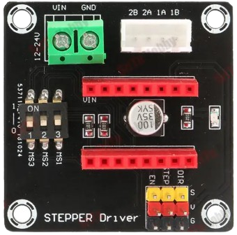
The Stepper Motor Driver Expansion Board is a circuit board designed to control stepper motors, providing the necessary power and signal connections to drive the motors with precision and control. It simplifies the process of interfacing stepper motors with microcontrollers or other control systems, making it an essential component for robotics, CNC machines, 3D printers, and other motion control applications.
Explore Projects Built with stepper motor driver expansion board

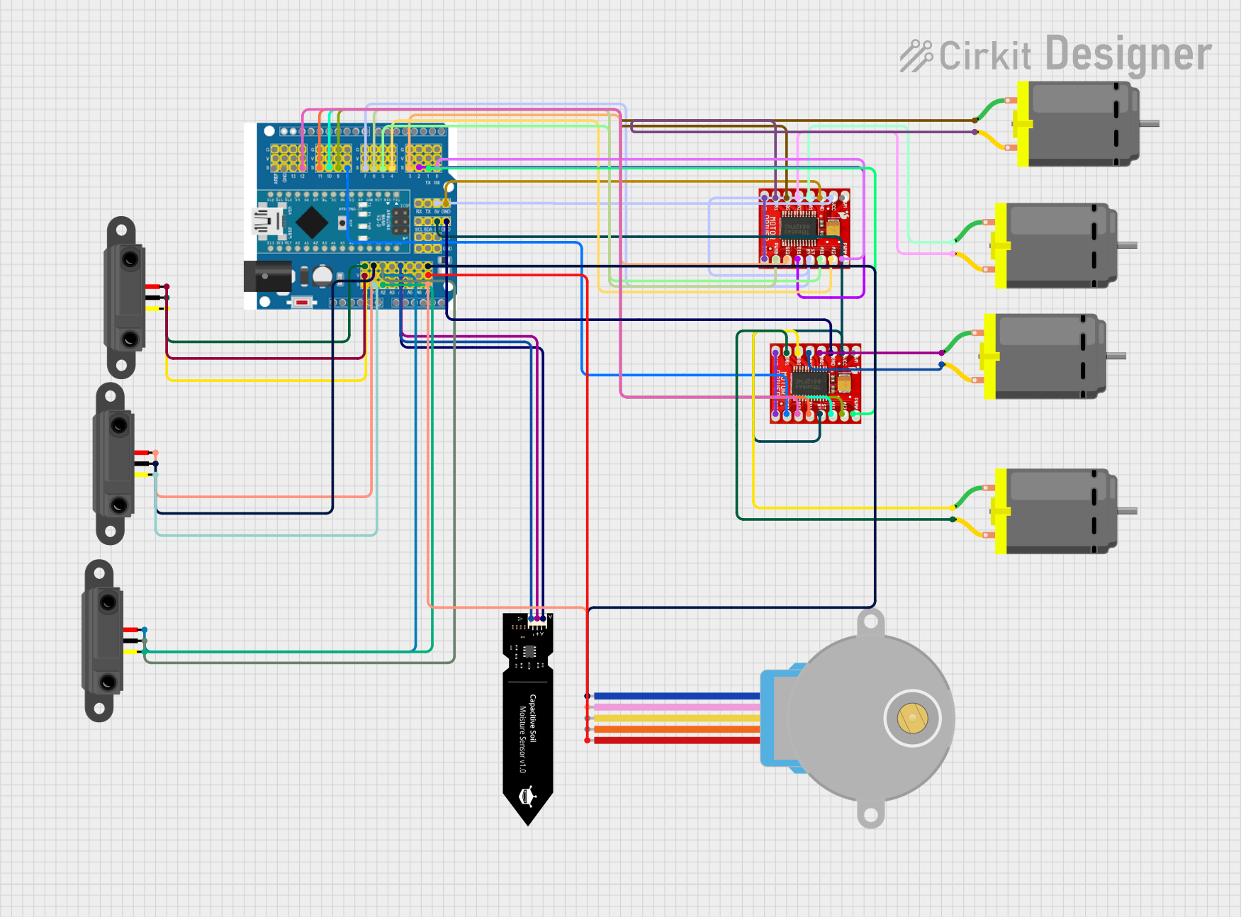

Explore Projects Built with stepper motor driver expansion board
Common Applications and Use Cases
- Robotics: Precise control of robotic arms and wheels.
- CNC Machines: Driving stepper motors for accurate cutting and engraving.
- 3D Printers: Controlling the movement of print heads and platforms.
- Automation Systems: Managing conveyor belts and other automated machinery.
- Educational Projects: Learning about motor control and motion systems.
Technical Specifications
Key Technical Details
- Input Voltage Range: 8V to 35V DC (varies by model)
- Output Current: Up to 2A per phase (adjustable via potentiometer)
- Microstepping Support: Full-step, half-step, 1/4-step, 1/8-step, 1/16-step (depending on driver IC)
- Control Interface: Step and direction signals
- Logic Voltage: 3.3V or 5V compatible
- Overcurrent Protection: Built-in
- Thermal Shutdown: Built-in
- Dimensions: Typically 60mm x 40mm (varies by model)
Pin Configuration and Descriptions
Input/Control Pins
| Pin Name | Description | Voltage Level |
|---|---|---|
VCC |
Power supply for the logic circuit | 3.3V or 5V |
GND |
Ground connection | 0V |
STEP |
Step pulse input for motor movement | 3.3V or 5V |
DIR |
Direction control input | 3.3V or 5V |
EN |
Enable/disable motor driver (active low) | 3.3V or 5V |
Motor Output Pins
| Pin Name | Description |
|---|---|
A+ |
Positive terminal for motor coil A |
A- |
Negative terminal for motor coil A |
B+ |
Positive terminal for motor coil B |
B- |
Negative terminal for motor coil B |
Power Input Pins
| Pin Name | Description | Voltage Level |
|---|---|---|
VMOT |
Motor power supply input | 8V to 35V DC |
GND |
Ground connection for motor power | 0V |
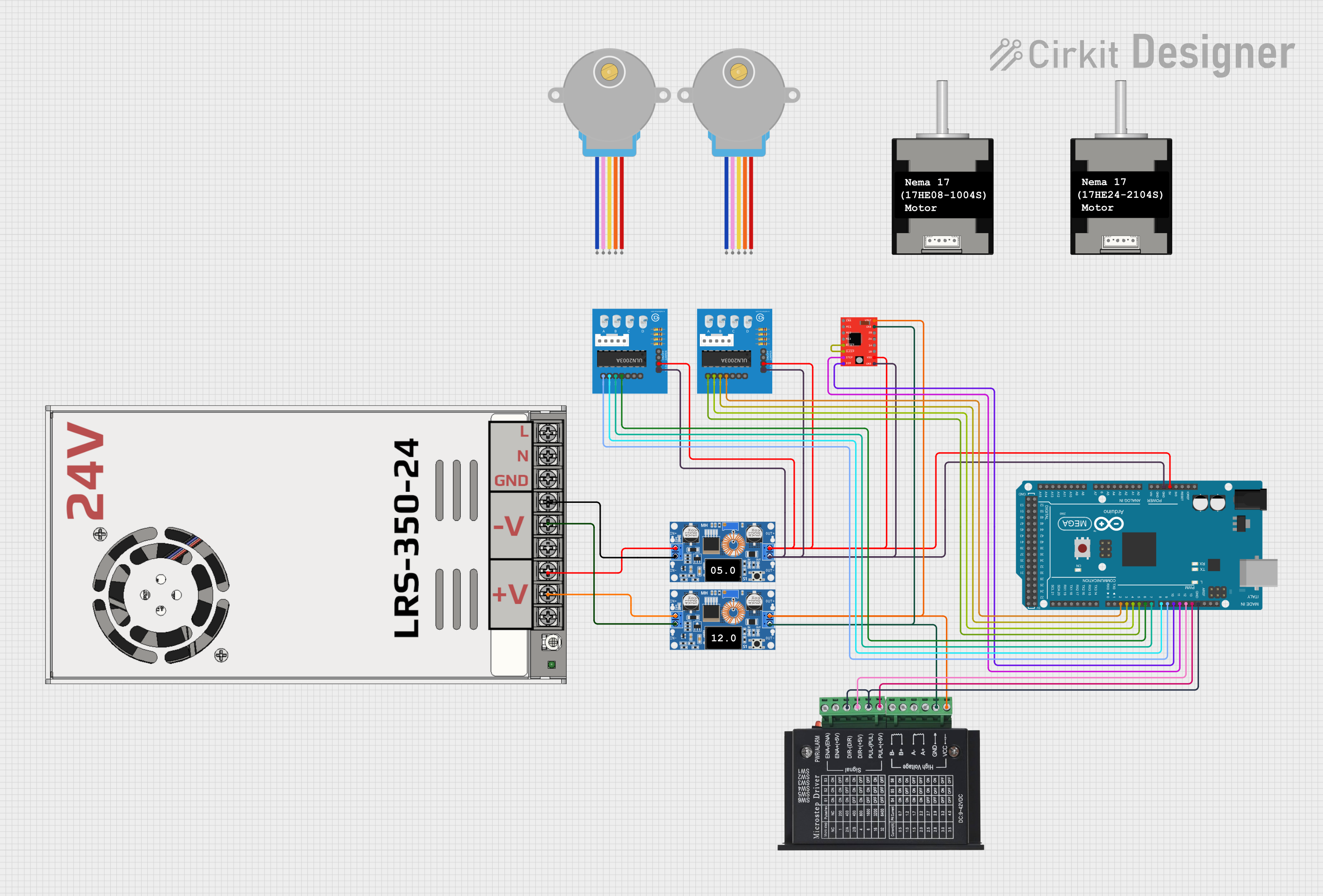
Usage Instructions
How to Use the Component in a Circuit
Power Connections:
- Connect the
VMOTpin to a DC power supply (8V to 35V) suitable for your stepper motor. - Connect the
GNDpin to the ground of the power supply.
- Connect the
Motor Connections:
- Connect the stepper motor's coil terminals to the
A+,A-,B+, andB-pins. Refer to your motor's datasheet to identify the correct coil pairs.
- Connect the stepper motor's coil terminals to the
Control Connections:
- Connect the
STEPandDIRpins to the corresponding output pins of your microcontroller. - Optionally, connect the
ENpin to enable or disable the driver as needed.
- Connect the
Logic Power:
- Connect the
VCCpin to the logic voltage (3.3V or 5V) of your microcontroller. - Ensure the
GNDpin is connected to the microcontroller's ground.
- Connect the
Adjust Current Limit:
- Use the onboard potentiometer to set the current limit according to your stepper motor's specifications. This prevents overheating and ensures optimal performance.
Microstepping Configuration:
- Configure the microstepping mode using the onboard jumpers or switches (if available). Refer to the board's datasheet for specific settings.
Important Considerations and Best Practices
- Always match the power supply voltage to the requirements of your stepper motor.
- Avoid disconnecting the motor while the driver is powered, as this can damage the driver.
- Use a heatsink or cooling fan if the driver operates at high currents for extended periods.
- Double-check all connections before powering the circuit to prevent short circuits or damage.
Example Code for Arduino UNO
// Example code to control a stepper motor using the Stepper Motor Driver Expansion Board
// Connect STEP to pin 2, DIR to pin 3, and EN to pin 4 on the Arduino UNO

#define STEP_PIN 2  // Pin connected to STEP input
#define DIR_PIN 3   // Pin connected to DIR input
#define EN_PIN 4    // Pin connected to EN input

void setup() {
  pinMode(STEP_PIN, OUTPUT); // Set STEP pin as output
  pinMode(DIR_PIN, OUTPUT);  // Set DIR pin as output
  pinMode(EN_PIN, OUTPUT);   // Set EN pin as output

  digitalWrite(EN_PIN, LOW); // Enable the motor driver (active low)
  digitalWrite(DIR_PIN, HIGH); // Set direction (HIGH for one direction, LOW for the other)
}

void loop() {
  // Generate step pulses to move the motor
  digitalWrite(STEP_PIN, HIGH); // Step pulse HIGH
  delayMicroseconds(500);       // Wait 500 microseconds
  digitalWrite(STEP_PIN, LOW);  // Step pulse LOW
  delayMicroseconds(500);       // Wait 500 microseconds
}
Troubleshooting and FAQs
Common Issues and Solutions
Motor Not Moving:
- Cause: Incorrect wiring or insufficient power supply.
- Solution: Verify all connections and ensure the power supply meets the motor's requirements.
Motor Vibrates but Doesn't Rotate:
- Cause: Incorrect coil connections.
- Solution: Check the motor's datasheet and ensure the coils are connected to the correct pins (
A+,A-,B+,B-).
Driver Overheating:
- Cause: Current limit set too high or inadequate cooling.
- Solution: Adjust the current limit using the potentiometer and add a heatsink or cooling fan.
Motor Moves Erratically:
- Cause: Noise or incorrect step pulse timing.
- Solution: Use shielded cables for control signals and ensure proper timing in the code.
FAQs
Can I use this board with a 12V stepper motor? Yes, as long as the power supply voltage is within the board's supported range (8V to 35V).
What happens if I exceed the current limit? The driver will activate overcurrent protection, but prolonged overcurrent can damage the board. Always set the current limit appropriately.
Can I control multiple stepper motors with one board? No, each board is designed to control a single stepper motor. Use multiple boards for multiple motors.
Is this board compatible with Raspberry Pi? Yes, the board can be controlled by any microcontroller or single-board computer that provides step and direction signals.