How to Use RPLiDAR A1M8 - R8: Examples, Pinouts, and Specs
Introduction
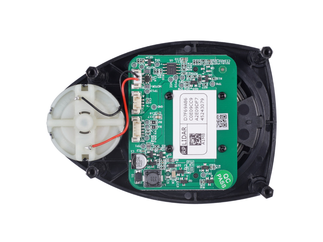
The RPLiDAR A1M8 - R8, manufactured by Slamtec (Part ID: A1M8-R6), is a 360-degree laser scanner designed for mapping and navigation applications. It uses laser triangulation to measure distances to surrounding objects, enabling the creation of high-resolution 2D and 3D maps. This compact and lightweight LiDAR is ideal for robotics, autonomous vehicles, and SLAM (Simultaneous Localization and Mapping) systems.
Explore Projects Built with RPLiDAR A1M8 - R8
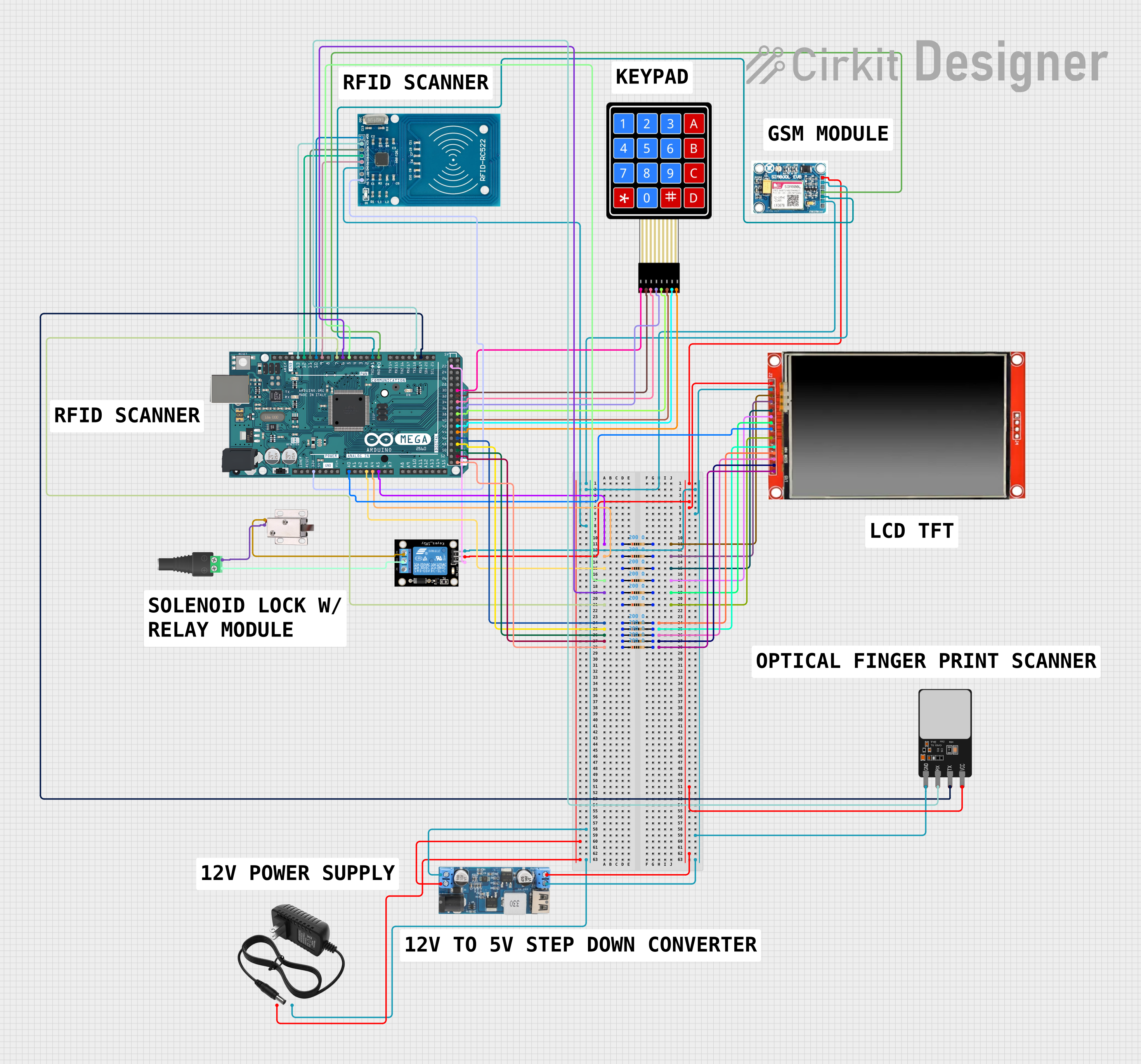
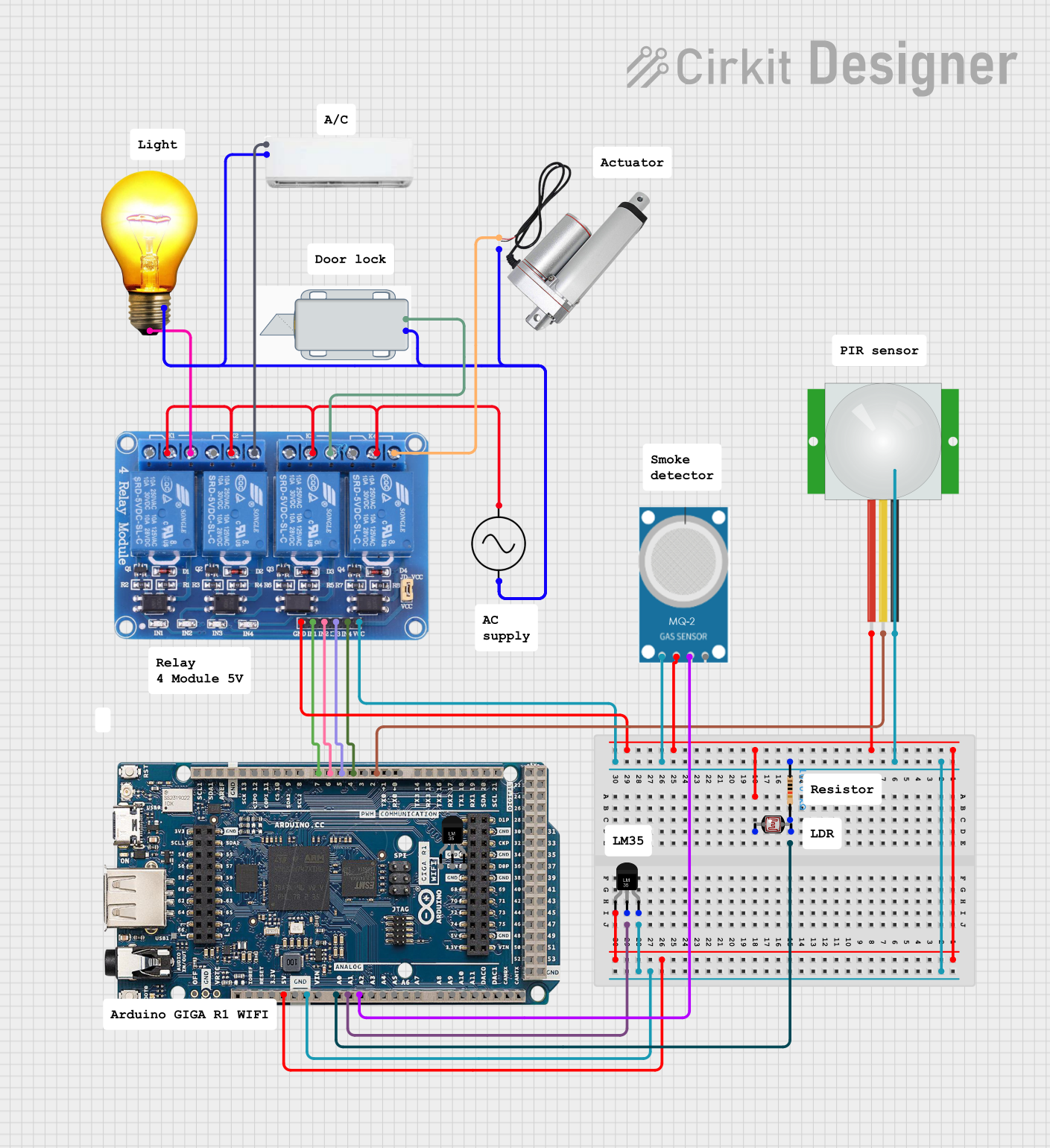
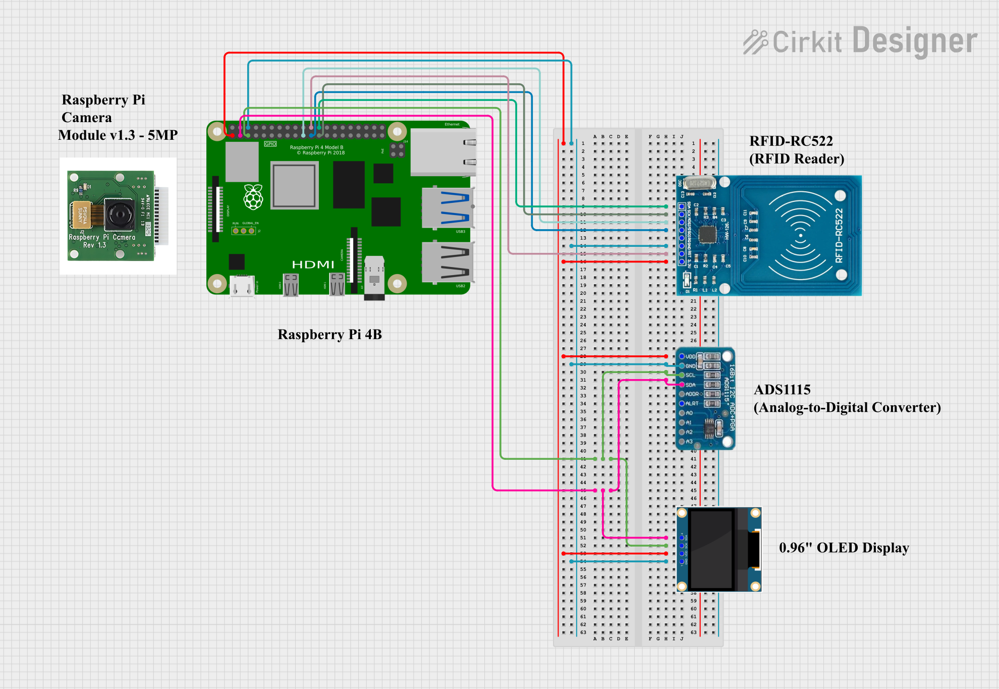
Explore Projects Built with RPLiDAR A1M8 - R8
Common Applications
- Autonomous navigation for robots and drones
- Indoor and outdoor mapping
- Obstacle detection and avoidance
- SLAM-based applications
- Smart home and IoT systems requiring spatial awareness
Technical Specifications
Key Technical Details
| Parameter | Value |
|---|---|
| Manufacturer | Slamtec |
| Model | A1M8-R8 |
| Part ID | A1M8-R6 |
| Scanning Range | 0.15 m to 12 m |
| Scanning Angle | 360° |
| Angular Resolution | 0.45° - 1.35° |
| Distance Resolution | <1% of the distance (typical) |
| Scanning Frequency | 5 Hz - 10 Hz (adjustable) |
| Laser Wavelength | 785 nm (infrared) |
| Laser Safety | Class 1 (eye-safe) |
| Communication Interface | UART (3.3V TTL) |
| Input Voltage | 5 V DC |
| Power Consumption | 2 W (typical) |
| Dimensions | 70 mm (diameter) x 41 mm (height) |
| Weight | 190 g |
Pin Configuration and Descriptions
The RPLiDAR A1M8 - R8 uses a 5-pin connector for power and communication. The pinout is as follows:
| Pin Number | Name | Description |
|---|---|---|
| 1 | VCC | Power input (5 V DC) |
| 2 | GND | Ground |
| 3 | TX | UART Transmit (3.3V TTL) |
| 4 | RX | UART Receive (3.3V TTL) |
| 5 | MOTOCTL | Motor control signal (PWM, 3.3V logic level) |
Usage Instructions
How to Use the RPLiDAR A1M8 - R8 in a Circuit
- Power Supply: Connect the VCC pin to a stable 5 V DC power source and the GND pin to ground.
- Communication: Use the TX and RX pins to interface with a microcontroller or computer via a UART connection. Ensure the UART logic level is 3.3V to avoid damaging the LiDAR.
- Motor Control: The MOTOCTL pin can be used to control the motor speed using a PWM signal. Alternatively, the motor can be powered directly by the LiDAR's internal controller.
- Data Processing: The LiDAR outputs distance and angle data via the UART interface. Use a compatible library or software to parse and visualize the data.
Important Considerations and Best Practices
- Laser Safety: Although the laser is Class 1 and eye-safe, avoid staring directly into the laser beam.
- Stable Power Supply: Use a regulated 5 V power source to ensure stable operation.
- UART Configuration: Set the UART baud rate to 115200 bps for communication.
- Environmental Conditions: The LiDAR performs best in environments with minimal ambient light interference and reflective surfaces.
- Mounting: Ensure the LiDAR is mounted securely and level to avoid measurement errors.
Example: Connecting to an Arduino UNO
The RPLiDAR A1M8 - R8 can be connected to an Arduino UNO for basic operation. Below is an example code snippet:
#include <SoftwareSerial.h>

// Define RX and TX pins for SoftwareSerial
SoftwareSerial lidarSerial(10, 11); // RX = Pin 10, TX = Pin 11

void setup() {
  Serial.begin(9600); // Initialize Serial Monitor
  lidarSerial.begin(115200); // Initialize LiDAR UART communication

  Serial.println("RPLiDAR A1M8 - R8 Initialized");
}

void loop() {
  if (lidarSerial.available()) {
    // Read data from LiDAR and forward it to Serial Monitor
    char data = lidarSerial.read();
    Serial.print(data);
  }
}
Note: Use a logic level shifter if connecting the LiDAR's 3.3V UART to the Arduino's 5V UART pins.
Troubleshooting and FAQs
Common Issues and Solutions
No Data Output:
- Ensure the LiDAR is powered correctly (5 V DC).
- Verify the UART connection and baud rate (115200 bps).
- Check for loose or incorrect wiring.
Inaccurate Measurements:
- Ensure the LiDAR is mounted securely and level.
- Avoid using the LiDAR in environments with excessive ambient light or highly reflective surfaces.
Motor Not Spinning:
- Verify the MOTOCTL pin is receiving a valid PWM signal.
- Check the power supply for sufficient current (at least 500 mA).
Interference with Other Devices:
- Ensure the LiDAR is not placed near devices emitting infrared light.
- Use shielding or physical separation to reduce interference.
FAQs
Q: Can the RPLiDAR A1M8 - R8 be used outdoors?
A: Yes, but performance may be affected by direct sunlight or rain. Use a protective enclosure for outdoor applications.
Q: What software can I use to visualize LiDAR data?
A: Slamtec provides an SDK and visualization tools. Alternatively, you can use ROS (Robot Operating System) for advanced applications.
Q: How do I adjust the scanning frequency?
A: The scanning frequency can be adjusted via software commands sent over the UART interface.
Q: Is the LiDAR compatible with Raspberry Pi?
A: Yes, the LiDAR can be connected to a Raspberry Pi via its UART interface. Use the Slamtec SDK or ROS for integration.