How to Use SparkFun 7-Segment Serial Display-Green: Examples, Pinouts, and Specs
Introduction
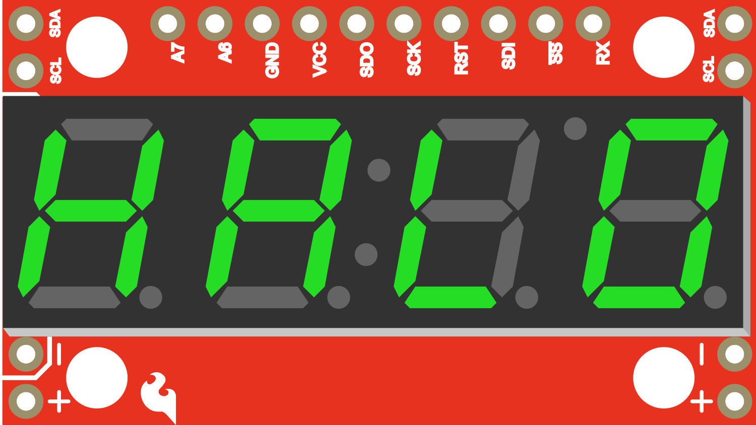
The SparkFun 7-Segment Serial Display - Green is a user-friendly LED display module that provides a simple way to add a 4-digit numeric display to your projects. It can be controlled via a serial interface, making it compatible with microcontrollers like the Arduino UNO. This display is commonly used in digital clocks, electronic meters, and other devices where numerical data needs to be shown.
Explore Projects Built with SparkFun 7-Segment Serial Display-Green
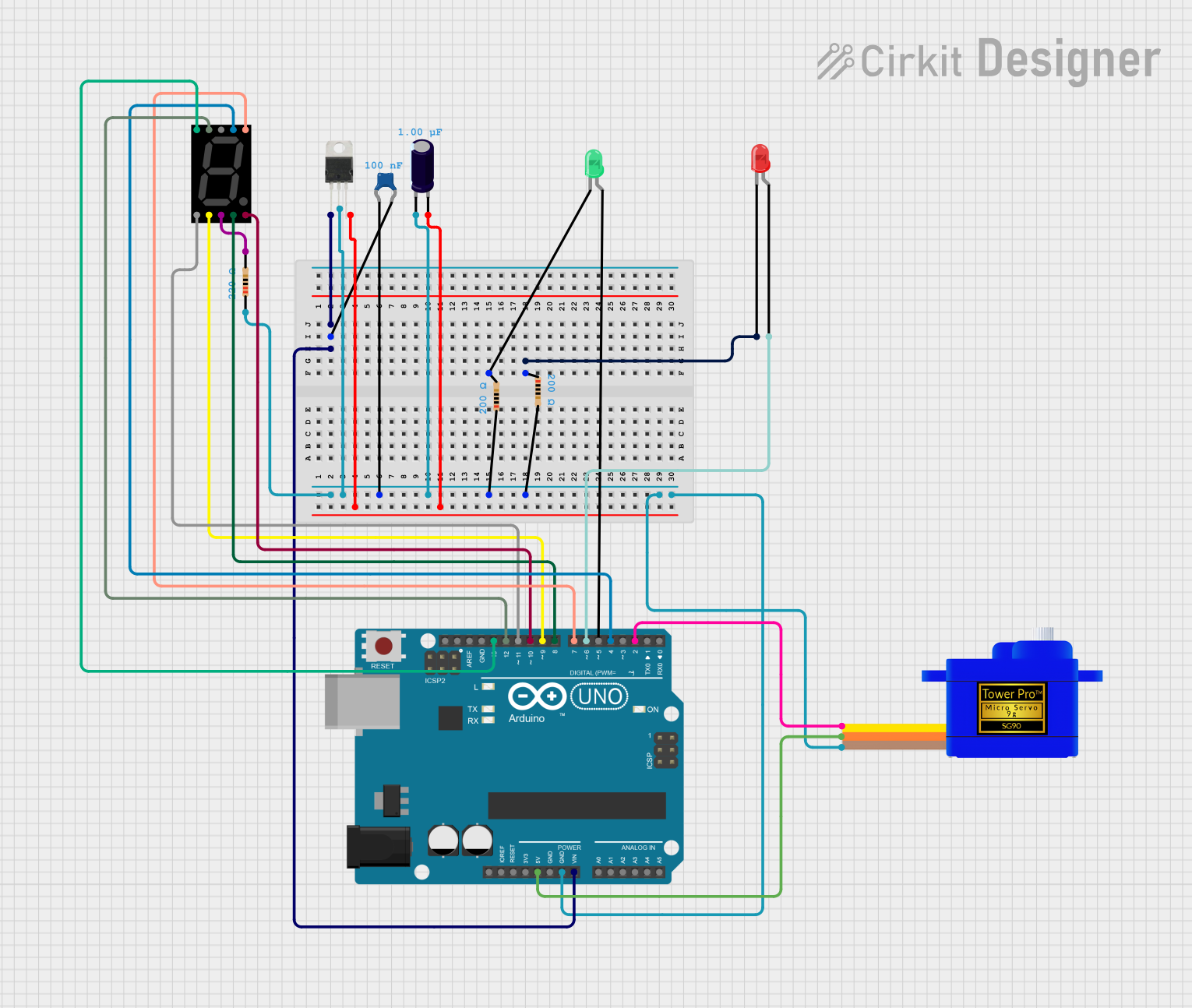
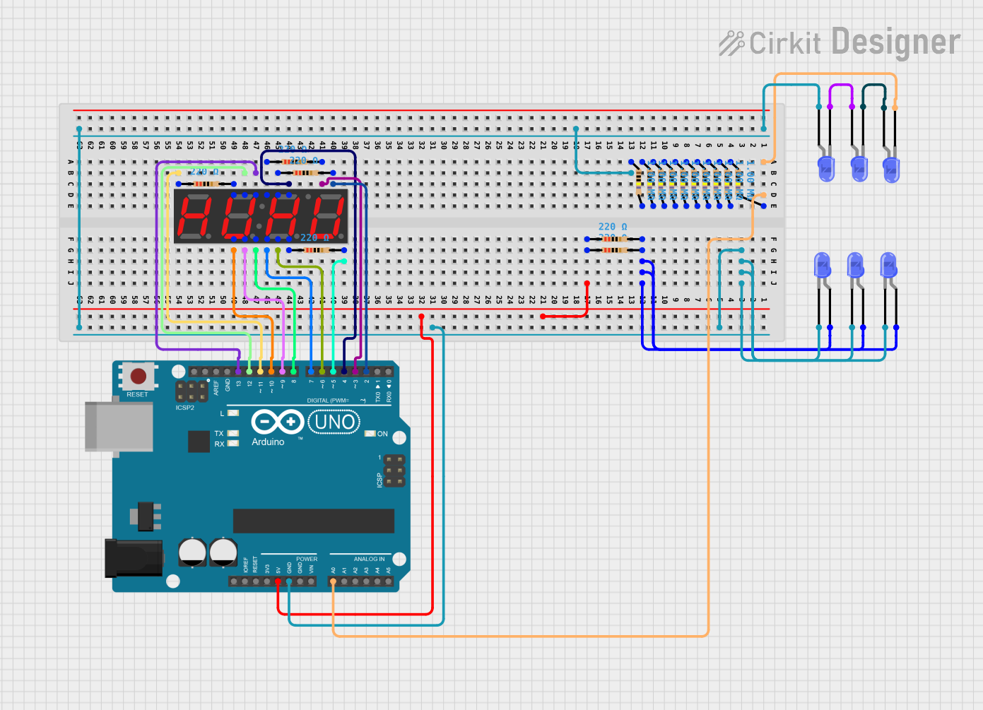
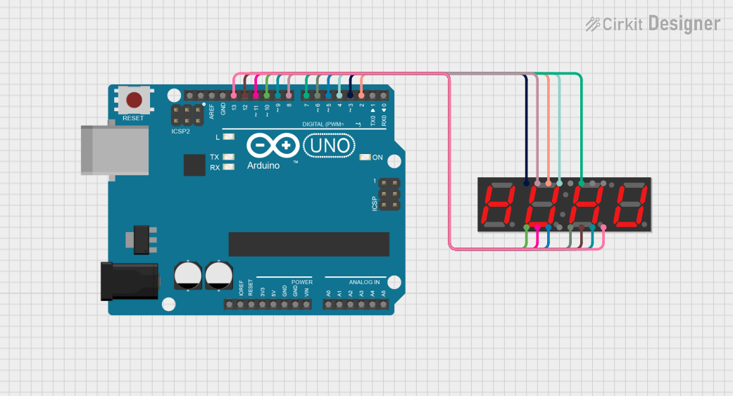
Explore Projects Built with SparkFun 7-Segment Serial Display-Green
Common Applications
- Digital clocks
- Electronic counters
- Scoreboards
- Timers
- Numeric displays for various projects
Technical Specifications
Key Technical Details
- Display Color: Green
- Operating Voltage: 3.3V to 6V
- Current Consumption: 20-40mA (normal operation)
- Communication: Serial interface
- Baud Rate: Default 9600 bps
Pin Configuration and Descriptions
| Pin Number | Name | Description |
|---|---|---|
| 1 | VCC | Power supply (3.3V to 6V) |
| 2 | GND | Ground connection |
| 3 | RX | Serial data input (TTL level) |
| 4 | TX | Serial data output (not used in all applications) |
Usage Instructions
How to Use the Component in a Circuit
- Powering the Display: Connect the VCC pin to a 3.3V to 6V power supply and the GND pin to the ground.
- Sending Data: Connect the RX pin to the TX pin of your microcontroller.
- Controlling Brightness: Send a serial command to adjust the brightness as needed.
Important Considerations and Best Practices
- Ensure that the power supply voltage does not exceed the maximum rating of 6V.
- Always connect the ground of the display to the ground of the microcontroller to ensure a common reference point.
- When sending serial data, ensure that the baud rate matches the display's default rate or the rate you have configured.
Example Code for Arduino UNO
#include <SoftwareSerial.h>

// RX and TX pins for software serial
#define DISPLAY_RX_PIN 10
#define DISPLAY_TX_PIN 11

// Set up a software serial port
SoftwareSerial displaySerial(DISPLAY_RX_PIN, DISPLAY_TX_PIN);

void setup() {
  // Start the software serial port at the baud rate of the display
  displaySerial.begin(9600);
}

void loop() {
  // Send a test number to the display
  displaySerial.print("1234");
  delay(1000); // Wait for a second

  // Clear the display
  displaySerial.write(0x76); // Clear command for the display
  delay(1000); // Wait for a second
}
Troubleshooting and FAQs
Common Issues
- Display Not Lighting Up: Check the power connections and ensure the voltage is within the specified range.
- Garbled or No Output: Verify that the baud rate of the microcontroller matches the display's baud rate.
- Partial Display: Ensure that all segments are functioning by sending a test sequence to light up all segments.
Solutions and Tips for Troubleshooting
- If the display is not lighting up, double-check the wiring, especially the VCC and GND connections.
- For garbled output, confirm that the serial communication settings are correct and that there are no loose connections.
- To test all segments, send the command to display all segments (usually by sending a specific character, refer to the display's datasheet).
FAQs
Q: Can I change the baud rate of the display? A: Yes, the baud rate can be changed by sending a specific command to the display.
Q: How do I control individual segments of the display? A: Individual segment control is usually done through specific serial commands. Refer to the datasheet for the command set.
Q: Is it possible to daisy-chain multiple displays? A: Some 7-segment serial displays support daisy-chaining. Check the datasheet for your specific model to see if this feature is supported and how to implement it.
Remember, this documentation is a starting point. For more detailed information, always refer to the manufacturer's datasheet and technical resources.