How to Use MLX90640 Adafruit Thermal Sensor: Examples, Pinouts, and Specs
Introduction
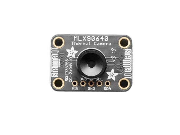
The MLX90640 Adafruit Thermal Sensor is a high-resolution infrared (IR) thermal camera module designed for non-contact temperature measurement and thermal imaging. Manufactured by Adafruit, this sensor features a 32x24 pixel IR sensor array, enabling it to detect temperature variations across a wide field of view. It is compact, versatile, and ideal for applications requiring precise thermal data.
Explore Projects Built with MLX90640 Adafruit Thermal Sensor
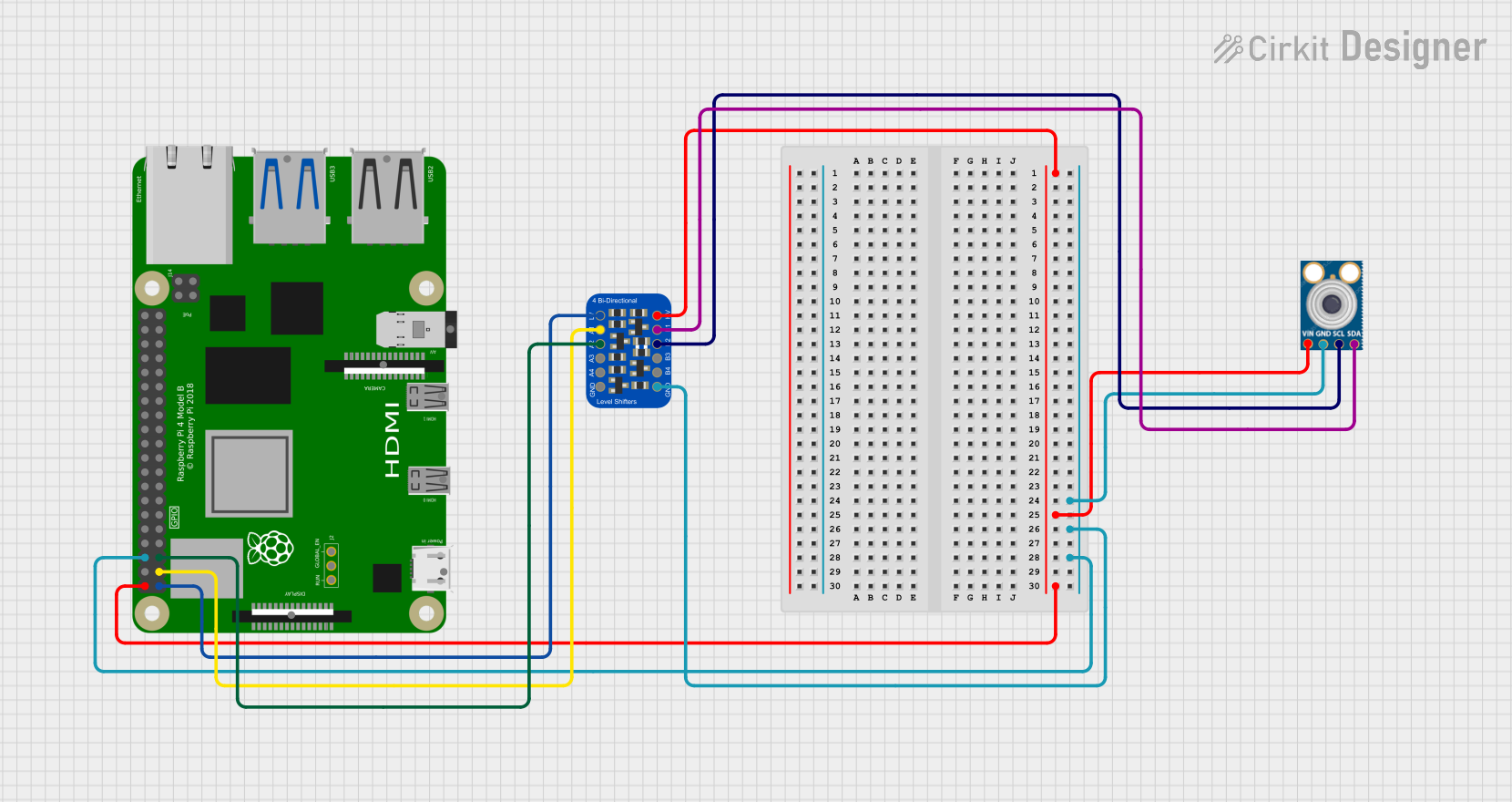
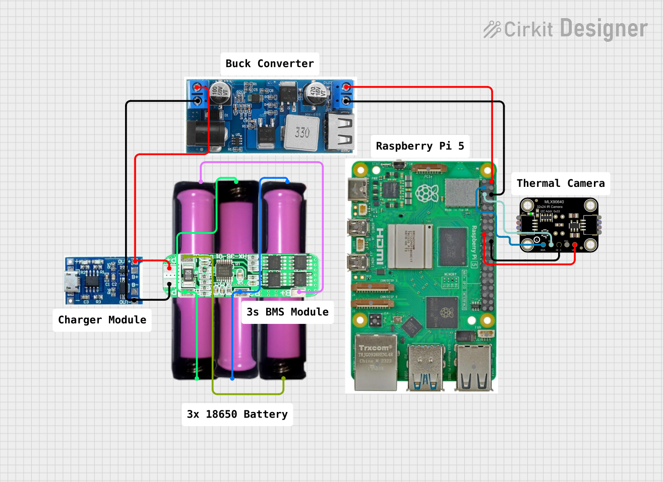
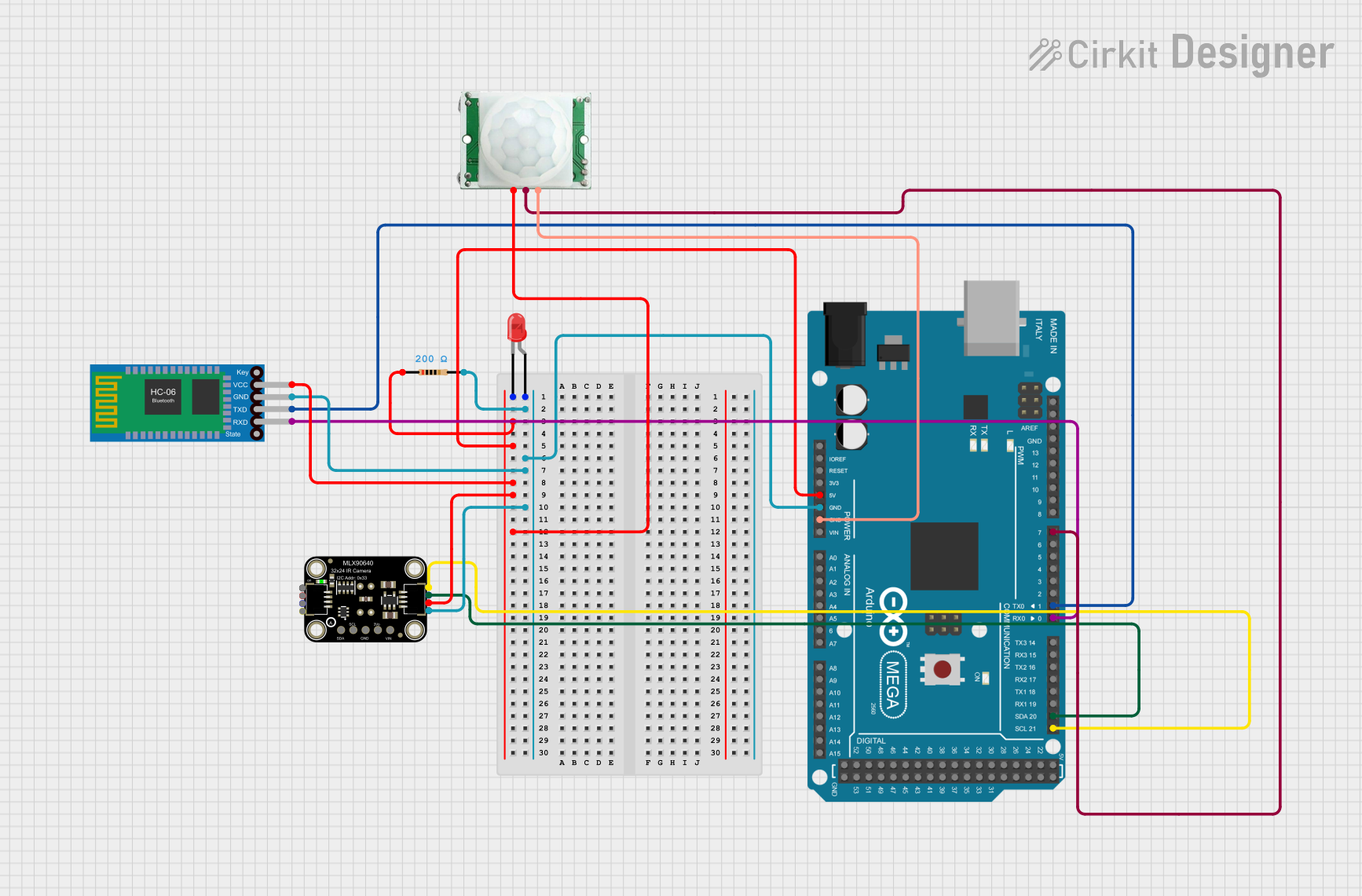
Explore Projects Built with MLX90640 Adafruit Thermal Sensor
Common Applications and Use Cases
- Robotics: Thermal mapping and obstacle detection.
- HVAC Systems: Monitoring temperature distribution and efficiency.
- Smart Home Systems: Detecting human presence or heat sources.
- Industrial Automation: Equipment monitoring and fault detection.
- Medical Devices: Non-contact temperature measurement.
- Research and Development: Thermal analysis and prototyping.
Technical Specifications
The following table outlines the key technical details of the MLX90640 Adafruit Thermal Sensor:
| Parameter | Value |
|---|---|
| Manufacturer | Adafruit |
| Part ID | Adafruit MLX90640 IR Thermal Camera |
| Sensor Resolution | 32x24 pixels |
| Field of View (FoV) | 55°x35° (Standard) or 110°x75° (Wide Angle) |
| Temperature Range | -40°C to 300°C |
| Accuracy | ±1°C (typical, for 0°C to 50°C range) |
| Interface | I2C |
| Operating Voltage | 3.3V to 5V |
| Current Consumption | ~23mA |
| Refresh Rate | 0.5Hz to 64Hz |
| Dimensions | 20mm x 20mm x 5mm |
Pin Configuration and Descriptions
The MLX90640 module has the following pinout:
| Pin | Name | Description |
|---|---|---|
| 1 | VIN | Power input (3.3V to 5V) |
| 2 | GND | Ground |
| 3 | SDA | I2C data line |
| 4 | SCL | I2C clock line |
Usage Instructions
How to Use the MLX90640 in a Circuit
- Power the Sensor: Connect the
VINpin to a 3.3V or 5V power source and theGNDpin to ground. - I2C Communication: Connect the
SDAandSCLpins to the corresponding I2C pins on your microcontroller (e.g., Arduino UNO). - Pull-Up Resistors: Ensure that the I2C lines have appropriate pull-up resistors (typically 4.7kΩ).
- Install Libraries: Use the Adafruit MLX90640 library for easy integration with Arduino or other platforms.
- Read Data: Use the library functions to read temperature data and process the thermal image.
Important Considerations and Best Practices
- Power Supply: Ensure a stable power supply to avoid noise in the thermal readings.
- I2C Address: The default I2C address is
0x33. If using multiple sensors, ensure address conflicts are resolved. - Refresh Rate: Higher refresh rates may increase power consumption.
- Ambient Conditions: Avoid direct sunlight or reflective surfaces, as they can affect accuracy.
- Calibration: The sensor is factory-calibrated, but additional calibration may be required for specific applications.
Example Code for Arduino UNO
Below is an example of how to use the MLX90640 with an Arduino UNO:
#include <Wire.h>
#include <Adafruit_MLX90640.h>

// Create an instance of the MLX90640 object
Adafruit_MLX90640 mlx;

// Define the frame buffer to store temperature data
float frame[32 * 24]; // 32x24 resolution

void setup() {
  Serial.begin(115200);
  while (!Serial); // Wait for Serial Monitor to open

  Serial.println("Initializing MLX90640...");

  // Initialize the MLX90640 sensor
  if (!mlx.begin(0x33)) { // Default I2C address is 0x33
    Serial.println("Failed to find MLX90640 sensor. Check wiring!");
    while (1);
  }

  // Set the refresh rate to 8Hz
  mlx.setMode(MLX90640_INTERLEAVED);
  mlx.setRefreshRate(MLX90640_8_HZ);

  Serial.println("MLX90640 initialized successfully!");
}

void loop() {
  // Read thermal data into the frame buffer
  if (mlx.getFrame(frame) != 0) {
    Serial.println("Failed to read frame data!");
    return;
  }

  // Print the temperature data
  for (int i = 0; i < 32 * 24; i++) {
    Serial.print(frame[i], 2); // Print temperature with 2 decimal places
    Serial.print(" ");
    if ((i + 1) % 32 == 0) { // Newline after every 32 pixels
      Serial.println();
    }
  }

  delay(125); // Delay to match the refresh rate (8Hz = 125ms)
}
Troubleshooting and FAQs
Common Issues and Solutions
Sensor Not Detected
- Cause: Incorrect wiring or I2C address mismatch.
- Solution: Verify the connections and ensure the I2C address matches the one in the code.
Inaccurate Temperature Readings
- Cause: Reflective surfaces or environmental interference.
- Solution: Avoid reflective surfaces and ensure the sensor is not exposed to direct sunlight.
Data Read Errors
- Cause: I2C communication issues.
- Solution: Check pull-up resistors on the I2C lines and ensure proper clock speed (typically 100kHz or 400kHz).
Slow Refresh Rate
- Cause: Default refresh rate is too low.
- Solution: Increase the refresh rate using the
setRefreshRate()function, but note the trade-off with power consumption.
FAQs
Can the MLX90640 detect humans? Yes, the sensor can detect humans based on their thermal signature.
What is the maximum distance for accurate readings? The effective range depends on the field of view and target size, but it is typically a few meters.
Can I use multiple MLX90640 sensors on the same I2C bus? Yes, but you must configure each sensor with a unique I2C address.
Is the sensor waterproof? No, the MLX90640 is not waterproof and should be protected from moisture.
Does the sensor require calibration? The sensor is factory-calibrated, but additional calibration may improve accuracy for specific applications.