How to Use DHT11-2: Examples, Pinouts, and Specs
Introduction
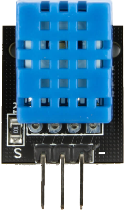
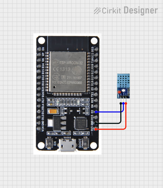
The DHT11-2 is a digital temperature and humidity sensor designed to provide accurate and reliable readings of environmental conditions. It features a single-wire communication interface, making it simple to integrate with microcontrollers and other digital systems. The DHT11-2 is widely used in applications such as weather stations, HVAC systems, greenhouses, and other projects requiring temperature and humidity monitoring.
Key features of the DHT11-2 include:
- Digital output for temperature and humidity data
- Compact design for easy integration
- Low power consumption
- Ideal for both hobbyist and professional applications
Explore Projects Built with DHT11-2
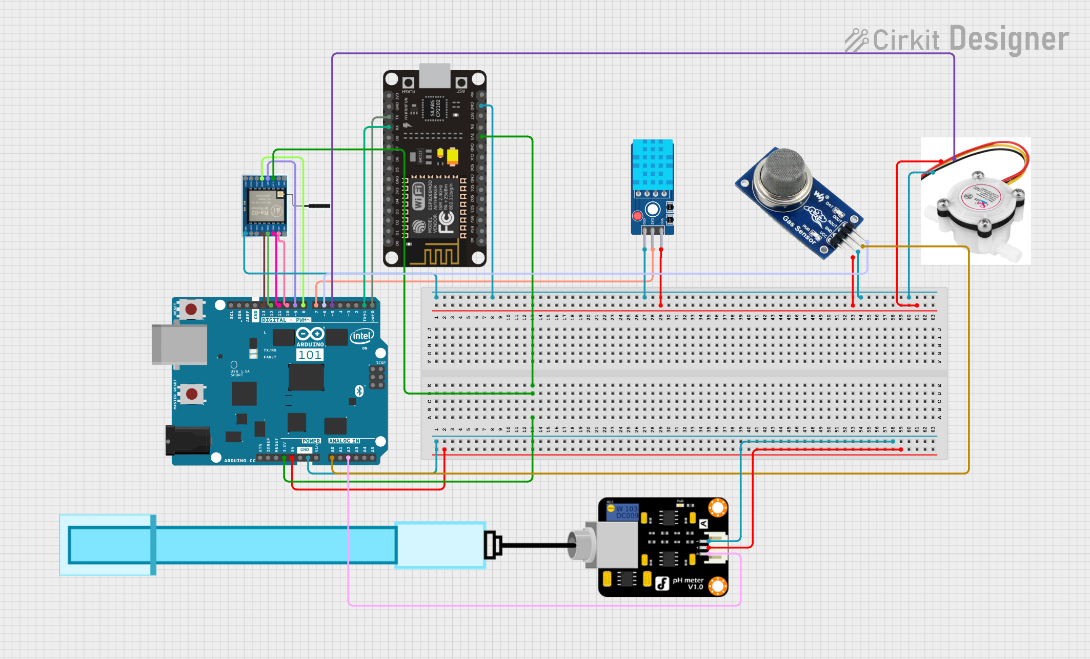
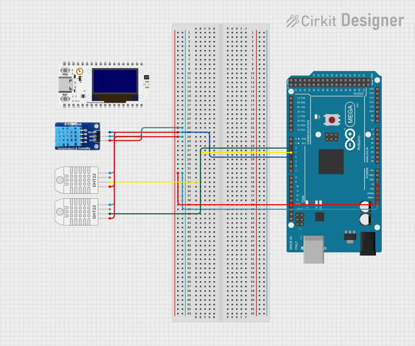
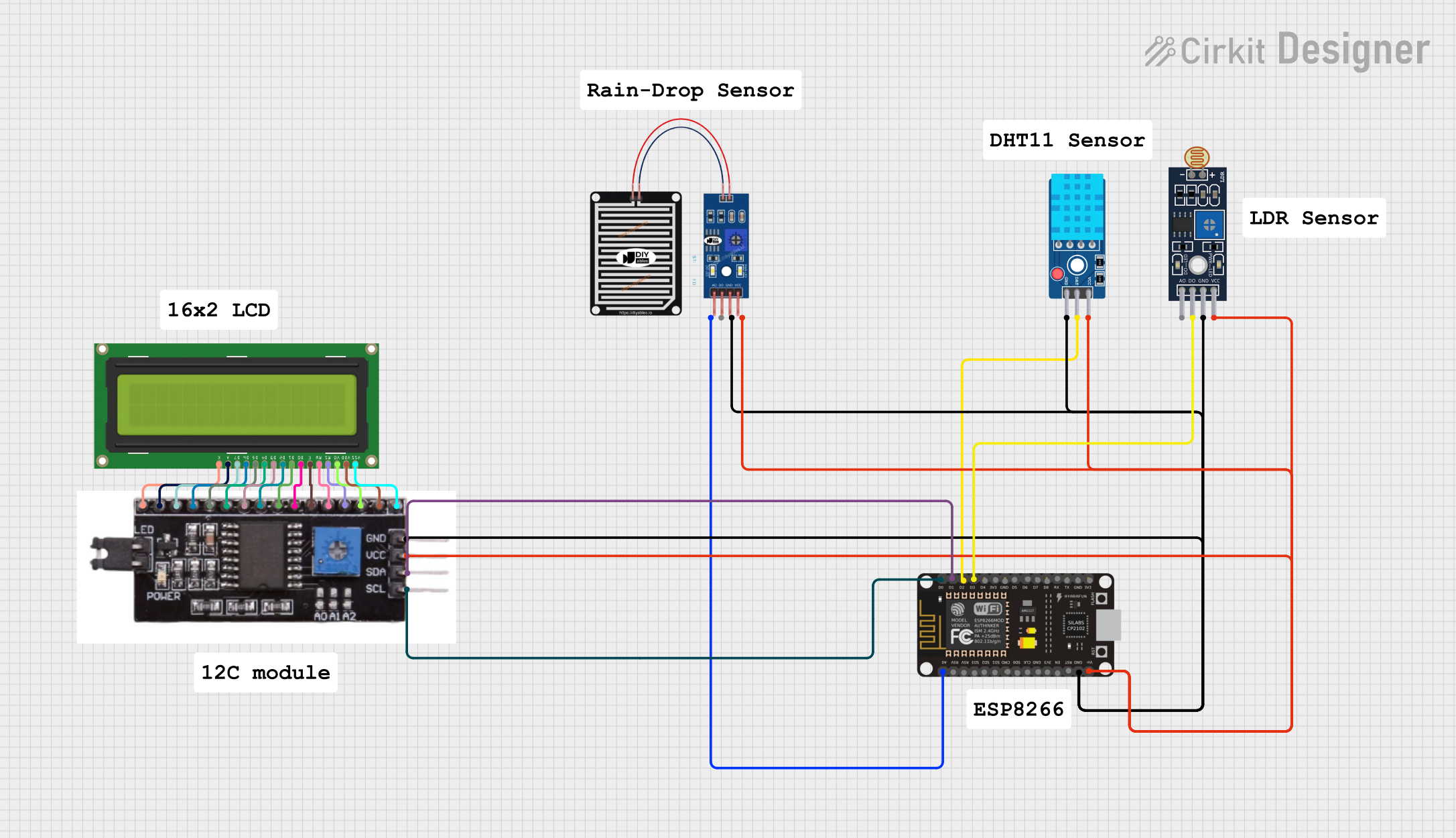
Explore Projects Built with DHT11-2
Technical Specifications
The DHT11-2 sensor has the following technical specifications:
| Parameter | Value |
|---|---|
| Operating Voltage | 3.3V to 5.5V |
| Temperature Range | 0°C to 50°C |
| Temperature Accuracy | ±2°C |
| Humidity Range | 20% to 90% RH |
| Humidity Accuracy | ±5% RH |
| Communication Protocol | Single-wire (digital) |
| Sampling Period | 1 second (minimum) |
| Dimensions | 15mm x 12mm x 5mm |
Pin Configuration
The DHT11-2 has four pins, as described in the table below:
| Pin Number | Name | Description |
|---|---|---|
| 1 | VCC | Power supply (3.3V to 5.5V) |
| 2 | DATA | Digital data output (connect to microcontroller) |
| 3 | NC | Not connected (leave unconnected) |
| 4 | GND | Ground |
Usage Instructions
Connecting the DHT11-2 to a Circuit
- Power Supply: Connect the VCC pin to a 3.3V or 5V power source and the GND pin to ground.
- Data Line: Connect the DATA pin to a digital input pin on your microcontroller. Use a 10kΩ pull-up resistor between the DATA pin and the VCC pin to ensure stable communication.
- NC Pin: Leave the NC pin unconnected.
Important Considerations
- Ensure the sensor is placed in an environment within its operating range (0°C to 50°C and 20% to 90% RH).
- Avoid exposing the sensor to water or condensation, as this may damage the internal circuitry.
- Allow a 1-second delay between consecutive readings to ensure accurate data.
Example Code for Arduino UNO
Below is an example of how to use the DHT11-2 with an Arduino UNO. This code requires the DHT library, which can be installed via the Arduino Library Manager.
#include <DHT.h>

// Define the pin connected to the DHT11-2 sensor
#define DHTPIN 2  // Connect DATA pin of DHT11-2 to digital pin 2

// Define the type of DHT sensor
#define DHTTYPE DHT11  // DHT11-2 is compatible with the DHT11 library

// Initialize the DHT sensor
DHT dht(DHTPIN, DHTTYPE);

void setup() {
  Serial.begin(9600);  // Start serial communication at 9600 baud
  Serial.println("DHT11-2 Sensor Test");
  dht.begin();  // Initialize the DHT sensor
}

void loop() {
  delay(2000);  // Wait 2 seconds between readings

  // Read temperature and humidity
  float humidity = dht.readHumidity();
  float temperature = dht.readTemperature();

  // Check if the readings are valid
  if (isnan(humidity) || isnan(temperature)) {
    Serial.println("Failed to read from DHT sensor!");
    return;
  }

  // Print the results to the Serial Monitor
  Serial.print("Humidity: ");
  Serial.print(humidity);
  Serial.print(" %\t");
  Serial.print("Temperature: ");
  Serial.print(temperature);
  Serial.println(" °C");
}
Best Practices
- Use a pull-up resistor (10kΩ) on the DATA line to ensure stable communication.
- Place the sensor in a location with good airflow for accurate readings.
- Avoid long wires between the sensor and the microcontroller to minimize signal degradation.
Troubleshooting and FAQs
Common Issues
No Data Output:
- Ensure the sensor is powered correctly (3.3V to 5.5V).
- Verify the pull-up resistor is connected between the DATA pin and VCC.
- Check the wiring and ensure the DATA pin is connected to the correct microcontroller pin.
Incorrect Readings:
- Ensure the sensor is operating within its specified temperature and humidity range.
- Avoid placing the sensor in direct sunlight or near heat sources.
- Allow the sensor to stabilize for a few seconds after powering it on.
"Failed to Read from DHT Sensor" Error:
- Verify the sensor is connected to the correct pin defined in the code.
- Check for loose or faulty connections.
FAQs
Q: Can the DHT11-2 measure negative temperatures?
A: No, the DHT11-2 can only measure temperatures in the range of 0°C to 50°C.
Q: How long does the sensor take to provide a reading?
A: The DHT11-2 requires a minimum sampling period of 1 second between readings.
Q: Can I use the DHT11-2 with a 3.3V microcontroller?
A: Yes, the DHT11-2 operates within a voltage range of 3.3V to 5.5V, making it compatible with 3.3V systems.
Q: Is the DHT11-2 waterproof?
A: No, the DHT11-2 is not waterproof and should not be exposed to water or condensation.