
How to Use TTL USR-TCP232-T2: Examples, Pinouts, and Specs
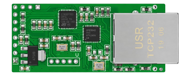
 Design with TTL USR-TCP232-T2 in Cirkit Designer
Introduction
The TTL USR-TCP232-T2 is a compact and efficient serial-to-TCP/IP converter module manufactured by Arduino. It enables seamless integration of serial devices into Ethernet networks, allowing for remote monitoring, control, and data exchange. This module supports a wide range of baud rates and can be configured through a user-friendly web interface. Its small size and versatile functionality make it ideal for applications such as industrial automation, IoT devices, and remote data acquisition systems.
Explore Projects Built with TTL USR-TCP232-T2
 Open Project in Cirkit Designer
 Open Project in Cirkit Designer
 Open Project in Cirkit Designer
 Open Project in Cirkit Designer
Explore Projects Built with TTL USR-TCP232-T2
Open Project in Cirkit DesignerOpen Project in Cirkit DesignerOpen Project in Cirkit DesignerOpen Project in Cirkit DesignerCommon Applications:
- Industrial automation and control systems
- IoT (Internet of Things) devices
- Remote monitoring and data logging
- Home automation systems
- Serial device networking (e.g., RS232/TTL devices)
Technical Specifications
Key Technical Details:
| Parameter | Specification |
|---|---|
| Manufacturer | Arduino |
| Manufacturer Part ID | TTL USR-TCP232-T2 |
| Communication Protocol | Serial (TTL) to TCP/IP |
| Baud Rate Range | 600 bps to 230.4 kbps |
| Network Interface | 10/100 Mbps Ethernet |
| Configuration Interface | Web-based or serial AT commands |
| Power Supply Voltage | 3.3V DC |
| Power Consumption | < 1W |
| Operating Temperature | -40°C to +85°C |
| Dimensions | 35mm x 15mm x 5mm |
Pin Configuration and Descriptions:
| Pin Name | Pin Number | Description |
|---|---|---|
| VCC | 1 | Power input (3.3V DC) |
| GND | 2 | Ground |
| TXD | 3 | Transmit data (TTL level) |
| RXD | 4 | Receive data (TTL level) |
| RST | 5 | Reset pin (active low) |
| ETH_TX+ | 6 | Ethernet transmit positive signal |
| ETH_TX- | 7 | Ethernet transmit negative signal |
| ETH_RX+ | 8 | Ethernet receive positive signal |
| ETH_RX- | 9 | Ethernet receive negative signal |
Usage Instructions
How to Use the TTL USR-TCP232-T2 in a Circuit:
- Power Supply: Connect the VCC pin to a 3.3V DC power source and the GND pin to ground.
- Serial Connection: Connect the TXD and RXD pins to the corresponding RX and TX pins of your microcontroller or serial device.
- Ethernet Connection: Connect the Ethernet pins (ETH_TX+, ETH_TX-, ETH_RX+, ETH_RX-) to an RJ45 Ethernet connector for network communication.
- Reset: Optionally, connect the RST pin to a push-button or microcontroller GPIO for resetting the module.
- Configuration:
- Access the module's web interface by connecting it to a network and entering its default IP address in a web browser.
- Alternatively, configure the module using serial AT commands via the TXD and RXD pins.
Important Considerations:
- Ensure the power supply voltage is strictly 3.3V to avoid damaging the module.
- Use proper Ethernet cabling and connectors to ensure reliable network communication.
- Configure the baud rate and network settings to match your application requirements.
- Avoid placing the module near high-frequency noise sources to maintain signal integrity.
Example: Connecting to an Arduino UNO
Below is an example of how to connect and use the TTL USR-TCP232-T2 with an Arduino UNO for serial-to-Ethernet communication.
Wiring:
| TTL USR-TCP232-T2 Pin | Arduino UNO Pin |
|---|---|
| VCC | 3.3V |
| GND | GND |
| TXD | Pin 10 (RX) |
| RXD | Pin 11 (TX) |
| RST | Not connected |
Arduino Code:
#include <SoftwareSerial.h>

// Define RX and TX pins for SoftwareSerial
SoftwareSerial mySerial(10, 11); // RX = Pin 10, TX = Pin 11

void setup() {
  // Initialize serial communication with the TTL module
  mySerial.begin(9600); // Set baud rate to match the module's configuration
  Serial.begin(9600);   // For debugging via Serial Monitor

  // Send a test message to the TTL module
  mySerial.println("Hello, TTL USR-TCP232-T2!");
  Serial.println("Message sent to TTL module.");
}

void loop() {
  // Check if data is available from the TTL module
  if (mySerial.available()) {
    String data = mySerial.readString(); // Read incoming data
    Serial.print("Received from TTL module: ");
    Serial.println(data); // Print data to Serial Monitor
  }

  // Check if data is available from the Serial Monitor
  if (Serial.available()) {
    String data = Serial.readString(); // Read user input
    mySerial.println(data); // Send data to the TTL module
  }
}
Troubleshooting and FAQs
Common Issues:
No Response from the Module:
- Ensure the module is powered with 3.3V DC.
- Verify the TXD and RXD connections are correct and not swapped.
- Check the baud rate configuration on both the module and the microcontroller.
Ethernet Connection Fails:
- Confirm the Ethernet cable is properly connected and functional.
- Verify the network settings (IP address, subnet mask, gateway) are correctly configured.
- Ensure the module is not blocked by a firewall or network restrictions.
Module Does Not Reset:
- Check if the RST pin is properly connected to ground for a brief moment.
- Ensure the reset signal is not held low for too long.
FAQs:
Q1: Can the module work with 5V logic levels?
A1: No, the TTL USR-TCP232-T2 operates at 3.3V logic levels. Use a level shifter if interfacing with 5V devices.
Q2: How do I restore the module to factory settings?
A2: Hold the RST pin low for 5 seconds while powering on the module. This will reset all settings to default.
Q3: What is the default IP address of the module?
A3: The default IP address is typically 192.168.0.7. Refer to the module's datasheet for confirmation.
Q4: Can I use this module for wireless communication?
A4: No, the TTL USR-TCP232-T2 is designed for wired Ethernet communication only.