How to Use PIC18F4685: Examples, Pinouts, and Specs
Introduction
The PIC18F4685 is an 8-bit microcontroller developed by Microchip Technology. It features a 16-bit instruction set, 64 KB of Flash memory, 3 KB of RAM, and a wide range of integrated peripherals. These include an Analog-to-Digital Converter (ADC), timers, and communication interfaces such as I2C, SPI, and UART. The PIC18F4685 is designed for high-performance embedded applications, offering a balance of processing power, memory, and peripheral integration.
Explore Projects Built with PIC18F4685


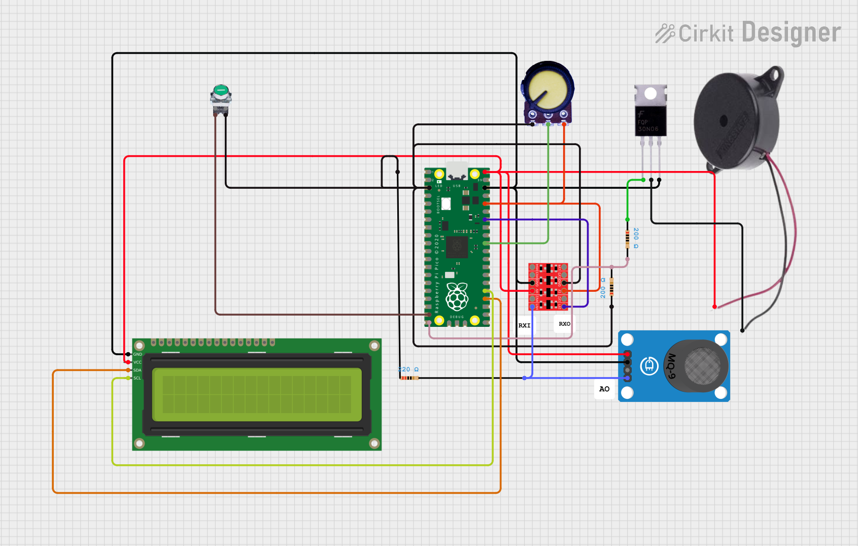
Explore Projects Built with PIC18F4685
Common Applications and Use Cases
- Industrial automation and control systems
- Home appliances and consumer electronics
- Automotive applications
- Data acquisition systems
- IoT devices and wireless communication modules
Technical Specifications
Key Technical Details
| Parameter | Value |
|---|---|
| CPU Architecture | 8-bit |
| Instruction Set | 16-bit |
| Flash Memory | 64 KB |
| RAM | 3 KB |
| Operating Voltage Range | 2.0V to 5.5V |
| Clock Speed | Up to 40 MHz (with external oscillator) |
| ADC Resolution | 10-bit |
| Number of ADC Channels | 11 |
| Communication Interfaces | I2C, SPI, UART, CAN |
| Timers | 4 (16-bit and 8-bit) |
| GPIO Pins | 36 |
| Package Options | 40-pin PDIP, 44-pin TQFP, 44-pin QFN |
Pin Configuration and Descriptions
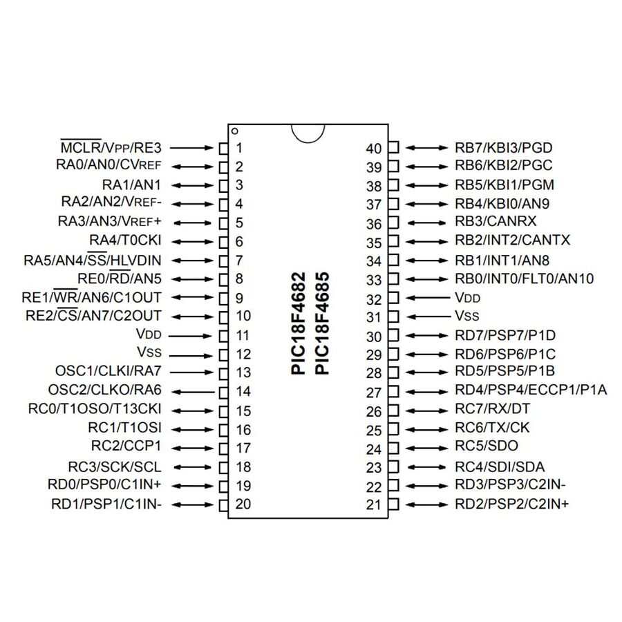
The PIC18F4685 is available in multiple package types. Below is the pin configuration for the 40-pin PDIP package:
| Pin Number | Pin Name | Description |
|---|---|---|
| 1 | MCLR/VPP | Master Clear (Reset) input or programming voltage |
| 2-5 | RA0-RA3 | Analog input or digital I/O |
| 6 | RA4 | Digital I/O or Timer0 clock input |
| 7 | RA5 | Digital I/O or analog input |
| 8-9 | RE0-RE1 | Digital I/O or analog input |
| 10 | RE2 | Digital I/O or analog input |
| 11-12 | VSS, VDD | Ground and Power Supply |
| 13-14 | OSC1, OSC2 | External oscillator pins |
| 15-16 | RC0-RC1 | Digital I/O or peripheral functions |
| 17-18 | RC2-RC3 | Digital I/O or peripheral functions |
| 19-20 | RC4-RC5 | Digital I/O or peripheral functions |
| 21-22 | RC6-RC7 | UART TX/RX or digital I/O |
| 23-24 | RD0-RD1 | Digital I/O or peripheral functions |
| 25-28 | RD2-RD5 | Digital I/O or peripheral functions |
| 29-30 | RD6-RD7 | Digital I/O or peripheral functions |
| 31-32 | RB0-RB1 | Digital I/O or interrupt inputs |
| 33-36 | RB2-RB5 | Digital I/O or interrupt inputs |
| 37-38 | RB6-RB7 | Digital I/O or programming/debugging pins |
| 39 | VSS | Ground |
| 40 | VDD | Power Supply |
Usage Instructions
How to Use the PIC18F4685 in a Circuit
- Power Supply: Connect the VDD pin to a 5V power source and the VSS pin to ground. Ensure proper decoupling capacitors (e.g., 0.1 µF) are placed near the power pins.
- Oscillator Configuration: Connect an external crystal oscillator to the OSC1 and OSC2 pins, or configure the internal oscillator if applicable.
- Reset Pin: Connect the MCLR pin to a pull-up resistor (e.g., 10 kΩ) to VDD. Optionally, add a push-button for manual reset.
- GPIO Configuration: Configure the GPIO pins as input or output in the software, depending on the application.
- Peripheral Setup: Initialize peripherals such as ADC, UART, I2C, or SPI in the firmware as needed.
Important Considerations and Best Practices
- Voltage Levels: Ensure the operating voltage is within the specified range (2.0V to 5.5V).
- Clock Source: Select an appropriate clock source for the desired performance and power consumption.
- Programming: Use a compatible programmer/debugger (e.g., PICkit 3 or MPLAB ICD) to program the microcontroller.
- Bypass Capacitors: Place bypass capacitors close to the power pins to reduce noise and improve stability.
- Unused Pins: Configure unused pins as outputs or connect them to ground through a resistor to avoid floating states.
Example Code for Arduino UNO Communication
The PIC18F4685 can communicate with an Arduino UNO via UART. Below is an example of Arduino code to send data to the PIC18F4685:
// Arduino UNO UART Communication with PIC18F4685
// Ensure the baud rate matches the PIC18F4685 configuration

void setup() {
  Serial.begin(9600); // Initialize UART at 9600 baud
}

void loop() {
  Serial.println("Hello, PIC18F4685!"); // Send data to PIC18F4685
  delay(1000); // Wait for 1 second
}
On the PIC18F4685 side, configure the UART module to receive the data and process it accordingly.
Troubleshooting and FAQs
Common Issues and Solutions
Microcontroller Not Responding
- Cause: Incorrect power supply or missing decoupling capacitors.
- Solution: Verify the power supply voltage and ensure proper decoupling capacitors are in place.
Programming Failure
- Cause: Incorrect programmer connection or unsupported device.
- Solution: Check the programmer connections and ensure the programmer supports the PIC18F4685.
Peripheral Not Working
- Cause: Incorrect initialization or configuration in the firmware.
- Solution: Double-check the peripheral initialization code and ensure the correct pins are used.
Floating Pins
- Cause: Unused pins left unconnected.
- Solution: Configure unused pins as outputs or connect them to ground through a resistor.
FAQs
Q: Can the PIC18F4685 operate at 3.3V?
A: Yes, the PIC18F4685 can operate at voltages as low as 2.0V, making it compatible with 3.3V systems.
Q: How do I select the internal oscillator?
A: Configure the oscillator settings in the configuration bits using MPLAB X IDE or a similar tool.
Q: What is the maximum clock speed of the PIC18F4685?
A: The maximum clock speed is 40 MHz when using an external oscillator.
Q: Can I use the PIC18F4685 for CAN communication?
A: Yes, the PIC18F4685 includes a built-in CAN module for Controller Area Network communication.