
How to Use load switching ATS points: Examples, Pinouts, and Specs

 Design with load switching ATS points in Cirkit Designer
Introduction
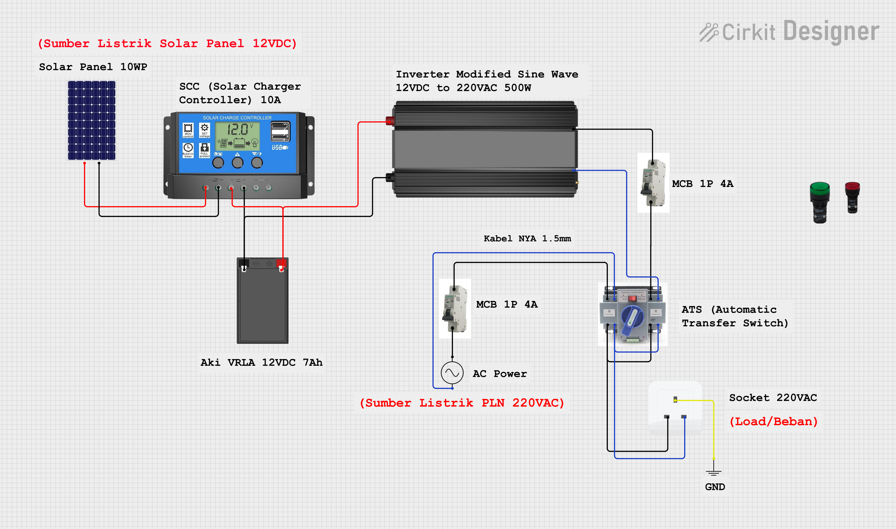
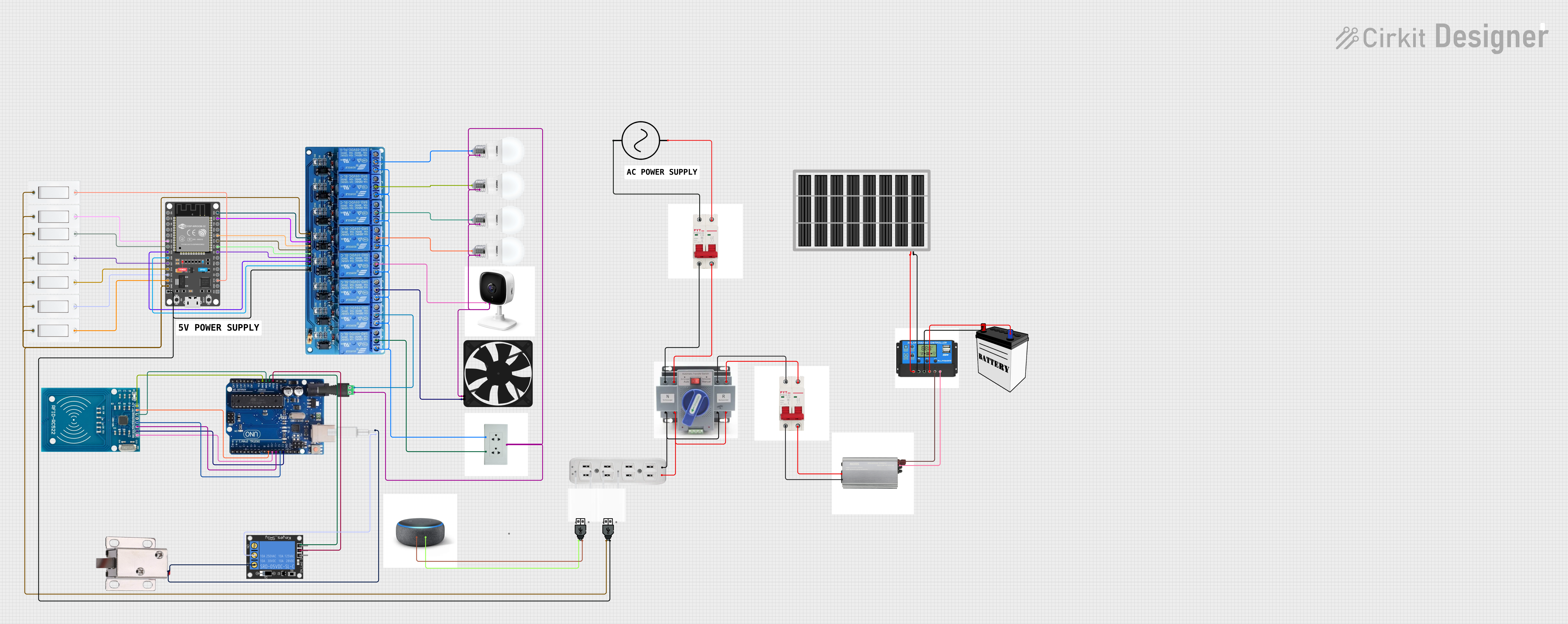
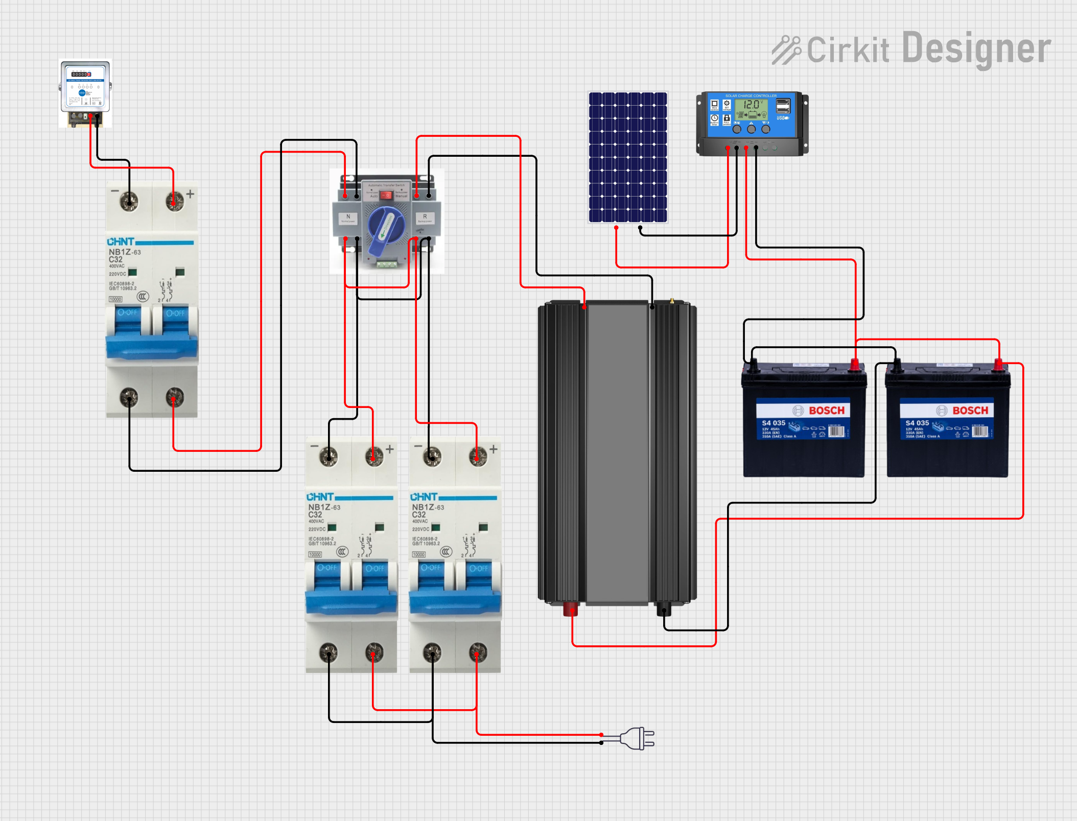
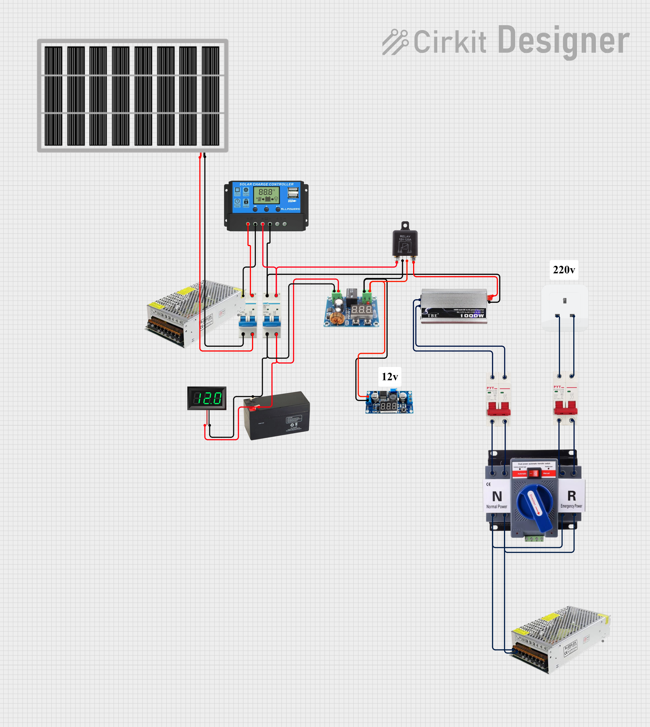
Load Switching Automatic Transfer Switch (ATS) points are critical components in electrical systems designed to ensure uninterrupted power supply. These points facilitate the automatic transfer of electrical loads between two power sources, such as a primary utility grid and a backup generator. When the primary power source fails or requires maintenance, the ATS points seamlessly switch the load to the secondary power source, minimizing downtime and maintaining operational continuity.
Explore Projects Built with load switching ATS points
 Open Project in Cirkit Designer
 Open Project in Cirkit Designer
 Open Project in Cirkit Designer
 Open Project in Cirkit Designer
Explore Projects Built with load switching ATS points
Open Project in Cirkit DesignerOpen Project in Cirkit DesignerOpen Project in Cirkit DesignerOpen Project in Cirkit DesignerCommon Applications and Use Cases
- Backup power systems for residential, commercial, and industrial facilities
- Data centers and server rooms requiring continuous power
- Hospitals and healthcare facilities with critical equipment
- Telecommunications infrastructure
- Renewable energy systems integrating solar or wind power with grid supply
Technical Specifications
Below are the general technical specifications for load switching ATS points. Specific values may vary depending on the manufacturer and model.
Key Technical Details
- Voltage Rating: 120V to 480V AC (varies by application)
- Current Rating: 10A to 4000A (depending on system requirements)
- Switching Time: Typically 1 to 10 seconds
- Control Voltage: 12V DC, 24V DC, or 230V AC (for control circuits)
- Operating Temperature: -20°C to 60°C
- Contact Type: Normally Open (NO) or Normally Closed (NC)
- Mechanical Durability: Up to 10,000 switching cycles
- Electrical Durability: Up to 5,000 switching cycles under full load
Pin Configuration and Descriptions
The pin configuration of ATS points depends on the specific design. Below is a general example of a 4-pin ATS point:
| Pin Number | Label | Description |
|---|---|---|
| 1 | Primary Input | Connects to the primary power source (e.g., utility grid). |
| 2 | Secondary Input | Connects to the secondary power source (e.g., generator or backup power). |
| 3 | Load Output | Connects to the electrical load (e.g., appliances, equipment, or circuits). |
| 4 | Control Signal | Receives the control signal to trigger the switching mechanism. |
Usage Instructions
How to Use the Component in a Circuit
Connect the Power Sources:
- Connect the primary power source (e.g., utility grid) to the
Primary Inputpin. - Connect the secondary power source (e.g., generator) to the
Secondary Inputpin.
- Connect the primary power source (e.g., utility grid) to the
Connect the Load:
- Attach the electrical load to the
Load Outputpin.
- Attach the electrical load to the
Control Signal Wiring:
- Wire the control signal to the
Control Signalpin. This signal determines when the ATS switches between power sources.
- Wire the control signal to the
Test the System:
- Simulate a power outage or manually disconnect the primary power source to verify that the ATS switches to the secondary source.
Monitor Performance:
- Regularly inspect the ATS for wear and ensure proper operation during routine maintenance.
Important Considerations and Best Practices
- Voltage and Current Ratings: Ensure the ATS points are rated for the voltage and current of your system.
- Control Signal Compatibility: Verify that the control signal voltage matches the ATS specifications.
- Grounding: Properly ground the ATS to prevent electrical hazards.
- Testing: Periodically test the ATS under load conditions to ensure reliable operation.
- Maintenance: Inspect the contacts and mechanical components for wear or damage.
Example: Connecting ATS Points to an Arduino UNO
If you are using an Arduino UNO to control the ATS points, you can use a digital output pin to send the control signal. Below is an example code snippet:
// Example code to control ATS points using Arduino UNO
const int controlPin = 7; // Pin connected to the ATS control signal

void setup() {
  pinMode(controlPin, OUTPUT); // Set the control pin as an output
}

void loop() {
  // Simulate switching to the secondary power source
  digitalWrite(controlPin, HIGH); // Send HIGH signal to ATS
  delay(5000); // Keep the secondary source active for 5 seconds

  // Switch back to the primary power source
  digitalWrite(controlPin, LOW); // Send LOW signal to ATS
  delay(5000); // Keep the primary source active for 5 seconds
}
Troubleshooting and FAQs
Common Issues Users Might Face
ATS Fails to Switch:
- Cause: Incorrect wiring or insufficient control signal voltage.
- Solution: Verify all connections and ensure the control signal matches the ATS specifications.
Delayed Switching:
- Cause: Mechanical wear or control circuit issues.
- Solution: Inspect the ATS mechanism and test the control circuit.
Frequent Switching:
- Cause: Unstable primary power source or incorrect control logic.
- Solution: Stabilize the primary power source or adjust the control logic to prevent unnecessary switching.
Overheating:
- Cause: Exceeding the current rating or poor ventilation.
- Solution: Ensure the ATS is rated for the load and improve ventilation around the component.
Solutions and Tips for Troubleshooting
- Check Connections: Ensure all wires are securely connected to the correct pins.
- Inspect Contacts: Look for signs of wear or pitting on the ATS contacts.
- Test Control Signal: Use a multimeter to verify the control signal voltage.
- Consult the Datasheet: Refer to the manufacturer's datasheet for specific troubleshooting steps.
By following this documentation, users can effectively integrate and maintain load switching ATS points in their electrical systems.