
How to Use Adafruit BeagleBone Proto Cape: Examples, Pinouts, and Specs
 Design with Adafruit BeagleBone Proto Cape in Cirkit Designer
Introduction
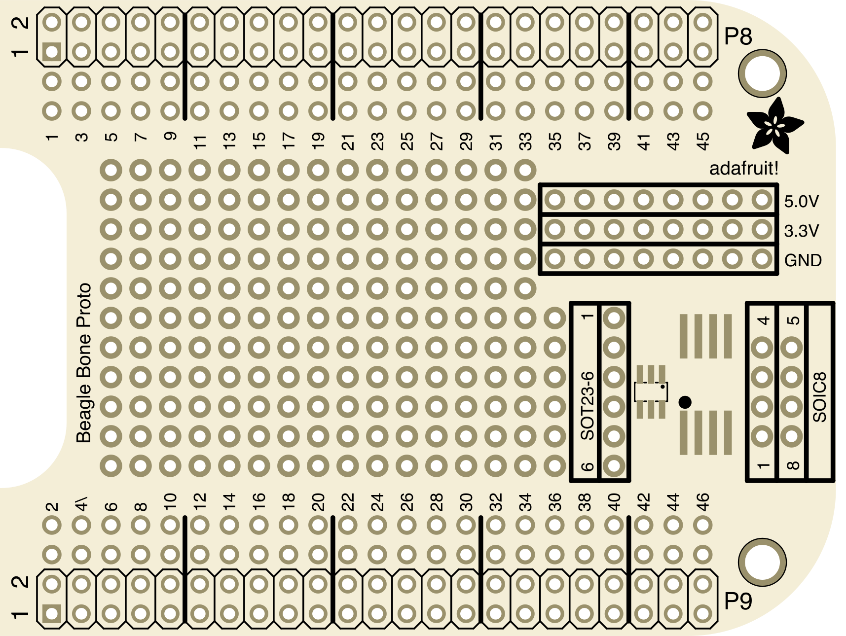
The Adafruit BeagleBone Proto Cape (Manufacturer Part ID: 572) is a prototyping add-on board designed specifically for the BeagleBone and BeagleBone Black. It provides a convenient breadboard area and additional GPIO pins, enabling users to create custom circuit designs and expand the functionality of their BeagleBone projects. This cape is ideal for prototyping, testing, and small-scale development.
Explore Projects Built with Adafruit BeagleBone Proto Cape
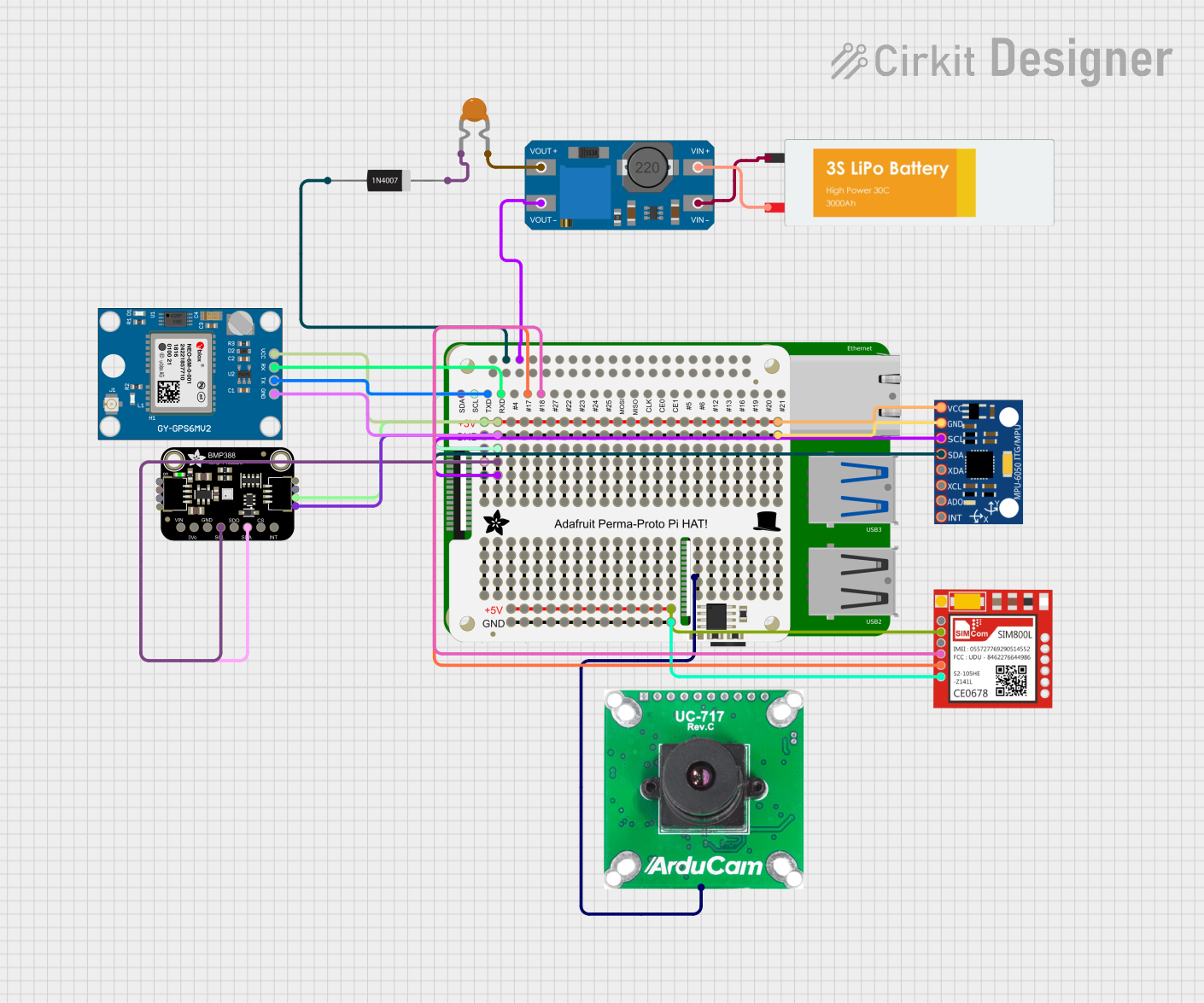 Open Project in Cirkit Designer
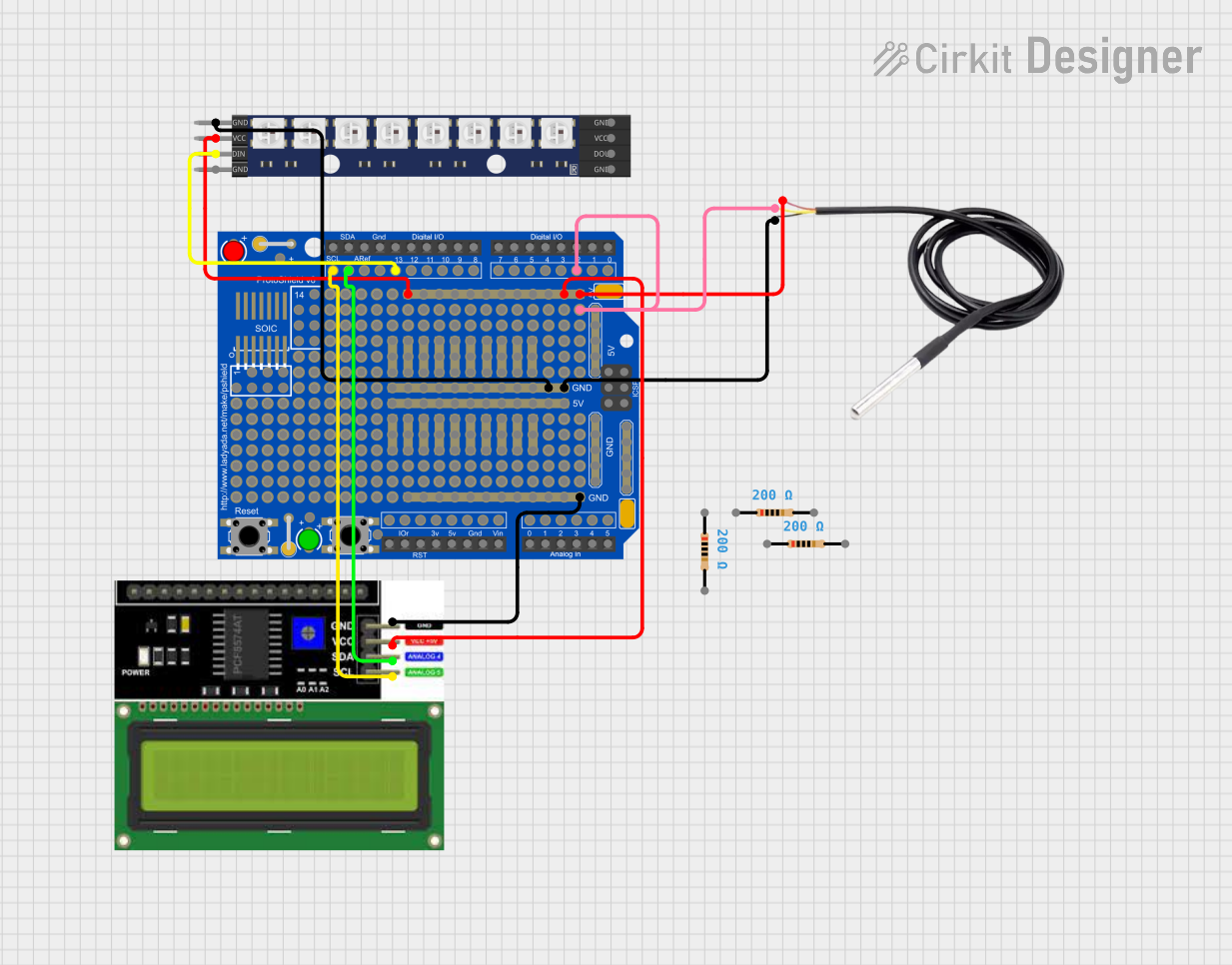 Open Project in Cirkit Designer
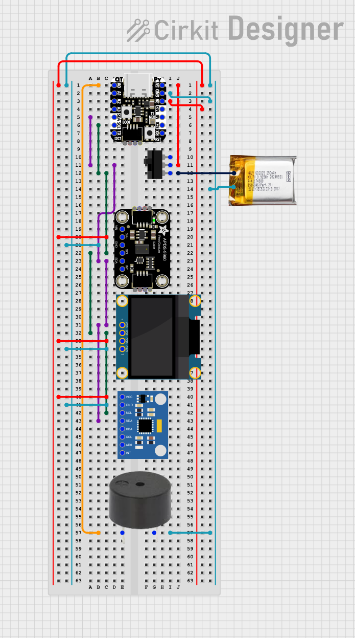 Open Project in Cirkit Designer
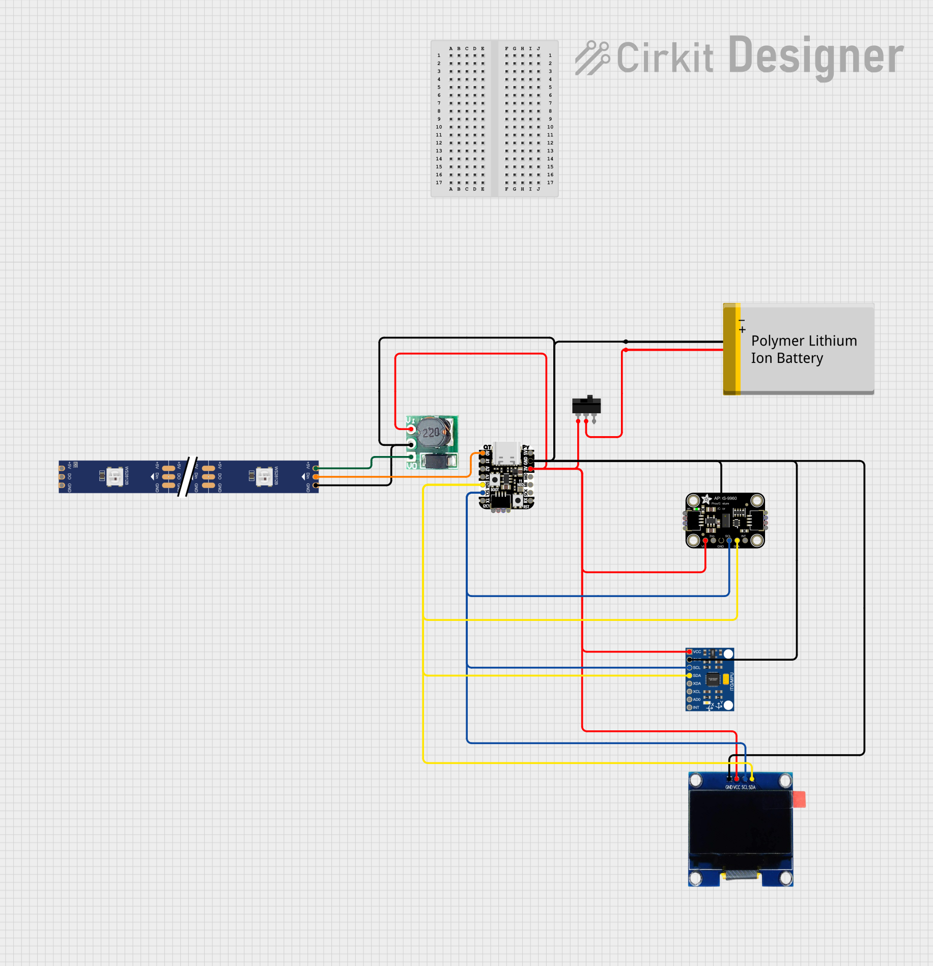 Open Project in Cirkit Designer
Explore Projects Built with Adafruit BeagleBone Proto Cape
Open Project in Cirkit DesignerOpen Project in Cirkit DesignerOpen Project in Cirkit DesignerOpen Project in Cirkit DesignerCommon Applications and Use Cases
- Rapid prototyping of custom circuits for BeagleBone projects.
- Extending GPIO access for sensors, actuators, and other peripherals.
- Educational projects and learning about hardware design.
- Building small-scale IoT devices or embedded systems.
Technical Specifications
The Adafruit BeagleBone Proto Cape is designed to integrate seamlessly with the BeagleBone platform. Below are its key technical details:
General Specifications
| Feature | Specification |
|---|---|
| Manufacturer | Adafruit |
| Part Number | 572 |
| Compatibility | BeagleBone, BeagleBone Black |
| Breadboard Area | 0.1" pitch prototyping area |
| GPIO Access | Breakout for all BeagleBone GPIO pins |
| Dimensions | 3.55" x 2.25" (90mm x 57mm) |
| Mounting | Includes mounting holes for secure attachment |
| Additional Features | EEPROM for cape identification |
Pin Configuration and Descriptions
The Proto Cape provides access to all BeagleBone GPIO pins via headers. Below is a summary of the pin configuration:
| Pin Header | Description |
|---|---|
| P8 | Access to BeagleBone GPIO pins P8 |
| P9 | Access to BeagleBone GPIO pins P9 |
| Breadboard | 0.1" pitch prototyping area for custom circuits |
Usage Instructions
How to Use the Adafruit BeagleBone Proto Cape
Attach the Cape to the BeagleBone:
- Align the Proto Cape's P8 and P9 headers with the corresponding headers on the BeagleBone.
- Gently press the cape onto the BeagleBone until it is securely connected.
Design Your Circuit:
- Use the breadboard area to design and build your custom circuit.
- Solder components directly onto the prototyping area or use jumper wires for temporary connections.
Access GPIO Pins:
- Use the P8 and P9 headers to connect your circuit to the BeagleBone's GPIO pins.
- Refer to the BeagleBone pinout diagram to identify specific GPIO pins for your application.
Power the BeagleBone:
- Power the BeagleBone as usual using a 5V DC power supply or USB connection.
Program the BeagleBone:
- Write and upload code to the BeagleBone to interact with your custom circuit.
- For example, you can use Python with the Adafruit_BBIO library to control GPIO pins.
Example Code for GPIO Control
Below is an example Python script to toggle an LED connected to a GPIO pin on the Proto Cape:
Import the Adafruit_BBIO library for GPIO control
import Adafruit_BBIO.GPIO as GPIO import time
Define the GPIO pin (P8_10 in this example)
led_pin = "P8_10"
Set up the GPIO pin as an output
GPIO.setup(led_pin, GPIO.OUT)
try: while True: GPIO.output(led_pin, GPIO.HIGH) # Turn the LED on time.sleep(1) # Wait for 1 second GPIO.output(led_pin, GPIO.LOW) # Turn the LED off time.sleep(1) # Wait for 1 second except KeyboardInterrupt: # Clean up GPIO settings when the script is interrupted GPIO.cleanup()
Important Considerations and Best Practices
- Soldering Tips: If you plan to make permanent connections, ensure proper soldering techniques to avoid short circuits.
- Pin Voltage Levels: BeagleBone GPIO pins operate at 3.3V logic levels. Avoid connecting 5V signals directly to GPIO pins to prevent damage.
- EEPROM Configuration: The cape includes an EEPROM for automatic identification by the BeagleBone. Ensure the EEPROM is not overwritten unless necessary.
Troubleshooting and FAQs
Common Issues and Solutions
Cape Not Detected by BeagleBone:
- Ensure the cape is properly seated on the BeagleBone headers.
- Verify that the EEPROM is correctly programmed and not corrupted.
GPIO Pins Not Responding:
- Check your circuit connections for loose wires or incorrect wiring.
- Confirm that the GPIO pin configuration in your code matches the physical connections.
Short Circuits on the Breadboard:
- Inspect the breadboard area for accidental solder bridges or misplaced components.
- Use a multimeter to test for continuity and identify shorts.
Power Issues:
- Ensure the BeagleBone is receiving sufficient power (5V DC).
- Avoid drawing excessive current from the GPIO pins.
FAQs
Q: Can I stack multiple Proto Capes on a single BeagleBone?
A: Stacking multiple Proto Capes is not recommended as it may block access to GPIO pins and cause mechanical instability.
Q: Is the breadboard area reusable?
A: The breadboard area is designed for soldering, so it is not reusable once components are soldered. For temporary connections, use jumper wires.
Q: Can I use the Proto Cape with other BeagleBone capes?
A: The Proto Cape can be used with other capes if there are no conflicts in GPIO pin usage or physical interference.
Q: Does the Proto Cape include any pre-soldered components?
A: No, the Proto Cape is a blank prototyping board and does not include pre-soldered components.
By following this documentation, you can effectively use the Adafruit BeagleBone Proto Cape to prototype and develop custom circuits for your BeagleBone projects.