Cirkit Designer Logo
Cirkit Designer
Your all-in-one circuit design IDE
Home / 
Component Documentation

How to Use MAX6682: Examples, Pinouts, and Specs

Image of MAX6682
Cirkit Designer LogoDesign with MAX6682 in Cirkit Designer

Introduction

The MAX6682, manufactured by Analog Devices, is a high-accuracy, low-power temperature sensor with a digital output. It communicates via a 2-wire I2C interface, making it easy to integrate into microcontroller-based systems. With a temperature range of -40°C to +125°C and a resolution of 0.0625°C, the MAX6682 is ideal for applications requiring precise temperature monitoring. Common use cases include industrial automation, HVAC systems, consumer electronics, and environmental monitoring.

Explore Projects Built with MAX6682

Use Cirkit Designer to design, explore, and prototype these projects online. Some projects support real-time simulation. Click "Open Project" to start designing instantly!
ESP8266 NodeMCU Controlled Multi-Channel Thermocouple Interface
Image of Temperature Data Acquisition_Task2: A project utilizing MAX6682 in a practical application
This circuit is designed to interface multiple MAX6675 thermocouple-to-digital converter modules with an ESP8266 NodeMCU microcontroller. Each MAX6675 module is connected to a temperature sensor and the ESP8266 is configured to communicate with the modules via SPI to read temperature data. The ESP8266 NodeMCU manages the chip select (CS) lines individually for each MAX6675 module, allowing for multiple temperature readings from different sensors.
Cirkit Designer LogoOpen Project in Cirkit Designer
Battery-Powered Health Monitoring System with Nucleo WB55RG and OLED Display
Image of Pulsefex: A project utilizing MAX6682 in a practical application
This circuit is a multi-sensor data acquisition system that uses a Nucleo WB55RG microcontroller to interface with a digital temperature sensor (TMP102), a pulse oximeter and heart-rate sensor (MAX30102), and a 0.96" OLED display via I2C. Additionally, it includes a Sim800l module for GSM communication, powered by a 3.7V LiPo battery.
Cirkit Designer LogoOpen Project in Cirkit Designer
Arduino Mega 2560 Based Multi-Channel Thermocouple Reader
Image of thermostat-test: A project utilizing MAX6682 in a practical application
This circuit is designed to interface with multiple MAX6675 thermocouple-to-digital converter modules using an Arduino Mega 2560 as the central processing unit. The Arduino reads temperature data from the MAX6675 modules over a shared SPI bus, with individual chip select (CS) lines for each module to enable multiplexing. The circuit is likely used for monitoring multiple temperature points, possibly in an industrial setting where precise temperature control and monitoring are critical.
Cirkit Designer LogoOpen Project in Cirkit Designer
ESP8266 NodeMCU with MAX6675 Thermocouple Interface for Temperature Monitoring
Image of UAS Metrin: A project utilizing MAX6682 in a practical application
This circuit is designed to measure temperature using a Type K thermocouple connected to a MAX6675 module, which digitizes the temperature reading. The MAX6675 module interfaces with an ESP8266 NodeMCU microcontroller over a SPI connection, using D5 (SCK), D6 (SO), and D8 (CS) for clock, data output, and chip select, respectively. The ESP8266 is responsible for processing the temperature data, which can then be used for monitoring, control, or communication purposes.
Cirkit Designer LogoOpen Project in Cirkit Designer

Explore Projects Built with MAX6682

Use Cirkit Designer to design, explore, and prototype these projects online. Some projects support real-time simulation. Click "Open Project" to start designing instantly!
Image of Temperature Data Acquisition_Task2: A project utilizing MAX6682 in a practical application
ESP8266 NodeMCU Controlled Multi-Channel Thermocouple Interface
This circuit is designed to interface multiple MAX6675 thermocouple-to-digital converter modules with an ESP8266 NodeMCU microcontroller. Each MAX6675 module is connected to a temperature sensor and the ESP8266 is configured to communicate with the modules via SPI to read temperature data. The ESP8266 NodeMCU manages the chip select (CS) lines individually for each MAX6675 module, allowing for multiple temperature readings from different sensors.
Cirkit Designer LogoOpen Project in Cirkit Designer
Image of Pulsefex: A project utilizing MAX6682 in a practical application
Battery-Powered Health Monitoring System with Nucleo WB55RG and OLED Display
This circuit is a multi-sensor data acquisition system that uses a Nucleo WB55RG microcontroller to interface with a digital temperature sensor (TMP102), a pulse oximeter and heart-rate sensor (MAX30102), and a 0.96" OLED display via I2C. Additionally, it includes a Sim800l module for GSM communication, powered by a 3.7V LiPo battery.
Cirkit Designer LogoOpen Project in Cirkit Designer
Image of thermostat-test: A project utilizing MAX6682 in a practical application
Arduino Mega 2560 Based Multi-Channel Thermocouple Reader
This circuit is designed to interface with multiple MAX6675 thermocouple-to-digital converter modules using an Arduino Mega 2560 as the central processing unit. The Arduino reads temperature data from the MAX6675 modules over a shared SPI bus, with individual chip select (CS) lines for each module to enable multiplexing. The circuit is likely used for monitoring multiple temperature points, possibly in an industrial setting where precise temperature control and monitoring are critical.
Cirkit Designer LogoOpen Project in Cirkit Designer
Image of UAS Metrin: A project utilizing MAX6682 in a practical application
ESP8266 NodeMCU with MAX6675 Thermocouple Interface for Temperature Monitoring
This circuit is designed to measure temperature using a Type K thermocouple connected to a MAX6675 module, which digitizes the temperature reading. The MAX6675 module interfaces with an ESP8266 NodeMCU microcontroller over a SPI connection, using D5 (SCK), D6 (SO), and D8 (CS) for clock, data output, and chip select, respectively. The ESP8266 is responsible for processing the temperature data, which can then be used for monitoring, control, or communication purposes.
Cirkit Designer LogoOpen Project in Cirkit Designer

Technical Specifications

The following table outlines the key technical details of the MAX6682:

Parameter Value
Supply Voltage (Vcc) 3.0V to 5.5V
Temperature Range -40°C to +125°C
Temperature Resolution 0.0625°C
Accuracy ±1°C (typical)
Communication Interface I2C (2-wire)
Current Consumption 250 µA (typical)
Output Format 12-bit digital temperature data
Package 8-pin SOIC

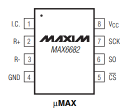
Pin Configuration and Descriptions

The MAX6682 is available in an 8-pin SOIC package. The pin configuration and descriptions are as follows:

Pin Number Pin Name Description
1 VCC Power supply input (3.0V to 5.5V)
2 GND Ground
3 SDA Serial Data Line for I2C communication
4 SCL Serial Clock Line for I2C communication
5 ALERT Over-temperature alert output (active low)
6 ADD0 I2C address selection bit 0
7 ADD1 I2C address selection bit 1
8 NC No connection (leave unconnected or grounded)

Usage Instructions

How to Use the MAX6682 in a Circuit

  1. Power Supply: Connect the VCC pin to a 3.0V to 5.5V power source and the GND pin to ground.
  2. I2C Communication: Connect the SDA and SCL pins to the corresponding I2C pins on your microcontroller. Use pull-up resistors (typically 4.7kΩ) on both SDA and SCL lines.
  3. Address Selection: Configure the I2C address by setting the ADD0 and ADD1 pins. These pins allow up to four unique I2C addresses.
  4. Alert Function: If needed, connect the ALERT pin to a microcontroller GPIO pin to monitor over-temperature conditions.
  5. Bypass Capacitor: Place a 0.1µF ceramic capacitor close to the VCC pin for power supply decoupling.

Important Considerations and Best Practices

  • Ensure proper pull-up resistors are used on the I2C lines to maintain signal integrity.
  • Avoid placing the MAX6682 near heat-generating components to ensure accurate temperature readings.
  • Use a stable power supply to minimize noise and fluctuations in temperature measurements.
  • If unused, leave the NC pin unconnected or tie it to ground.

Example Code for Arduino UNO

Below is an example of how to interface the MAX6682 with an Arduino UNO using the Wire library:

#include <Wire.h>

#define MAX6682_ADDRESS 0x48  // Default I2C address of the MAX6682

void setup() {
  Wire.begin();               // Initialize I2C communication
  Serial.begin(9600);         // Initialize serial communication for debugging
}

void loop() {
  float temperature = readTemperature();
  Serial.print("Temperature: ");
  Serial.print(temperature);
  Serial.println(" °C");
  delay(1000);                // Wait 1 second before the next reading
}

float readTemperature() {
  Wire.beginTransmission(MAX6682_ADDRESS);
  Wire.write(0x00);           // Point to the temperature register
  Wire.endTransmission();
  
  Wire.requestFrom(MAX6682_ADDRESS, 2);  // Request 2 bytes of temperature data
  if (Wire.available() == 2) {
    int msb = Wire.read();    // Most significant byte
    int lsb = Wire.read();    // Least significant byte
    
    // Combine MSB and LSB, then convert to temperature
    int16_t rawTemp = (msb << 8) | lsb;
    return rawTemp * 0.0625;  // Convert to Celsius (resolution is 0.0625°C)
  }
  return NAN;                 // Return NaN if data is unavailable
}

Troubleshooting and FAQs

Common Issues and Solutions

  1. No Temperature Data Received

    • Cause: Incorrect I2C address or wiring.
    • Solution: Verify the I2C address and ensure proper connections for SDA and SCL lines.
  2. Inaccurate Temperature Readings

    • Cause: Heat sources near the sensor or unstable power supply.
    • Solution: Relocate the sensor away from heat sources and use a decoupling capacitor on the VCC pin.
  3. I2C Communication Errors

    • Cause: Missing or incorrect pull-up resistors on SDA and SCL lines.
    • Solution: Add 4.7kΩ pull-up resistors to the SDA and SCL lines.
  4. ALERT Pin Not Functioning

    • Cause: ALERT pin not connected or configured.
    • Solution: Ensure the ALERT pin is connected to a GPIO pin and properly configured in the microcontroller firmware.

FAQs

Q: Can the MAX6682 operate at 3.3V?
A: Yes, the MAX6682 supports a supply voltage range of 3.0V to 5.5V, making it compatible with 3.3V systems.

Q: How do I calculate the temperature from raw data?
A: The raw 12-bit data can be converted to temperature by multiplying it by the resolution (0.0625°C).

Q: What is the maximum I2C clock speed supported?
A: The MAX6682 supports I2C clock speeds up to 400kHz (Fast Mode).

Q: Can I use multiple MAX6682 sensors on the same I2C bus?
A: Yes, you can use up to four MAX6682 sensors by configuring the ADD0 and ADD1 pins to set unique I2C addresses.