How to Use WeMos LOLIN D32 V1.0.0 ESP-32 WiFi-Bluetooth Combo: Examples, Pinouts, and Specs
Introduction
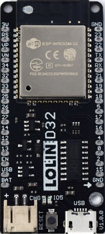
The WeMos LOLIN D32 V1.0.0 (ESP-WROOM-32) is a powerful and versatile development board designed by WEMOS/LOLIN. It is based on the ESP32 chip, which integrates dual-core processing, WiFi, and Bluetooth capabilities. This board is ideal for Internet of Things (IoT) projects, wireless communication, and applications requiring high performance and connectivity.
Explore Projects Built with WeMos LOLIN D32 V1.0.0 ESP-32 WiFi-Bluetooth Combo


Explore Projects Built with WeMos LOLIN D32 V1.0.0 ESP-32 WiFi-Bluetooth Combo
Common Applications and Use Cases
- IoT devices and smart home automation
- Wireless sensor networks
- Bluetooth Low Energy (BLE) applications
- Robotics and remote control systems
- Data logging and real-time monitoring
- Prototyping and development of connected devices
Technical Specifications
The following table outlines the key technical specifications of the LOLIN D32 V1.0.0:
| Specification | Details |
|---|---|
| Microcontroller | ESP32 (ESP-WROOM-32 module) |
| CPU | Dual-core Xtensa® 32-bit LX6, up to 240 MHz |
| Flash Memory | 4 MB (SPI Flash) |
| SRAM | 520 KB |
| Wireless Connectivity | WiFi 802.11 b/g/n, Bluetooth v4.2 (Classic + BLE) |
| Operating Voltage | 3.3V |
| Input Voltage Range | 5V (via USB) or 3.3V (via 3V3 pin) |
| GPIO Pins | 26 GPIO pins (including ADC, DAC, PWM, I2C, SPI, UART) |
| ADC Resolution | 12-bit |
| DAC Resolution | 8-bit |
| USB Interface | Micro-USB |
| Dimensions | 50 mm x 25.4 mm |
| Power Consumption | Ultra-low power consumption in deep sleep mode (as low as 10 µA) |
| Operating Temperature | -40°C to +85°C |
Pin Configuration and Descriptions
The LOLIN D32 V1.0.0 features a 30-pin layout. Below is the pin configuration:
| Pin | Name | Description |
|---|---|---|
| 1 | GND | Ground |
| 2 | 3V3 | 3.3V power output |
| 3 | EN | Enable pin (active high, used to reset the chip) |
| 4 | IO23 | GPIO23 (supports ADC, PWM, SPI, etc.) |
| 5 | IO22 | GPIO22 (supports I2C SCL, ADC, PWM, etc.) |
| 6 | IO21 | GPIO21 (supports I2C SDA, ADC, PWM, etc.) |
| 7 | IO19 | GPIO19 (supports SPI, ADC, PWM, etc.) |
| 8 | IO18 | GPIO18 (supports SPI, ADC, PWM, etc.) |
| 9 | IO17 | GPIO17 (supports UART, ADC, PWM, etc.) |
| 10 | IO16 | GPIO16 (supports ADC, PWM, etc.) |
| 11 | IO15 | GPIO15 (supports ADC, PWM, etc.) |
| 12 | IO14 | GPIO14 (supports ADC, PWM, etc.) |
| 13 | IO13 | GPIO13 (supports ADC, PWM, etc.) |
| 14 | IO12 | GPIO12 (supports ADC, PWM, etc.) |
| 15 | IO11 | GPIO11 (supports ADC, PWM, etc.) |
| 16 | IO10 | GPIO10 (supports ADC, PWM, etc.) |
| 17 | IO9 | GPIO9 (supports ADC, PWM, etc.) |
| 18 | IO8 | GPIO8 (supports ADC, PWM, etc.) |
| 19 | IO7 | GPIO7 (supports ADC, PWM, etc.) |
| 20 | IO6 | GPIO6 (supports ADC, PWM, etc.) |
| 21 | IO5 | GPIO5 (supports ADC, PWM, etc.) |
| 22 | IO4 | GPIO4 (supports ADC, PWM, etc.) |
| 23 | IO3 | GPIO3 (supports ADC, PWM, etc.) |
| 24 | IO2 | GPIO2 (supports ADC, PWM, etc.) |
| 25 | IO1 | GPIO1 (supports ADC, PWM, etc.) |
| 26 | IO0 | GPIO0 (supports ADC, PWM, etc.) |
| 27 | VIN | Input voltage (5V via USB or external power supply) |
| 28 | TXD0 | UART0 Transmit |
| 29 | RXD0 | UART0 Receive |
| 30 | RST | Reset pin |
Usage Instructions
How to Use the Component in a Circuit
Powering the Board:
- Connect the board to a computer or USB power source using a Micro-USB cable.
- Alternatively, supply 3.3V to the 3V3 pin or 5V to the VIN pin.
Programming the Board:
- Install the Arduino IDE and add the ESP32 board support via the Board Manager.
- Select "LOLIN D32" as the board type in the Arduino IDE.
- Connect the board to your computer and select the appropriate COM port.
Connecting Peripherals:
- Use the GPIO pins to connect sensors, actuators, or other peripherals.
- Ensure that the voltage levels of connected devices are compatible with the 3.3V logic of the ESP32.
Uploading Code:
- Write or load a sketch in the Arduino IDE.
- Click the "Upload" button to flash the code to the board.
Important Considerations and Best Practices
- Voltage Levels: The GPIO pins operate at 3.3V. Avoid applying 5V directly to the pins to prevent damage.
- Deep Sleep Mode: Use deep sleep mode to minimize power consumption in battery-powered applications.
- Pin Multiplexing: Many GPIO pins have multiple functions (e.g., ADC, PWM, I2C). Refer to the ESP32 datasheet for details.
- External Antenna: For better WiFi performance, ensure the onboard antenna is not obstructed.
Example Code for Arduino UNO Integration
Below is an example of using the LOLIN D32 to blink an LED connected to GPIO2:
// Example: Blink an LED connected to GPIO2 on the LOLIN D32

void setup() {
  pinMode(2, OUTPUT); // Set GPIO2 as an output pin
}

void loop() {
  digitalWrite(2, HIGH); // Turn the LED on
  delay(1000);           // Wait for 1 second
  digitalWrite(2, LOW);  // Turn the LED off
  delay(1000);           // Wait for 1 second
}
Troubleshooting and FAQs
Common Issues and Solutions
Board Not Detected in Arduino IDE:
- Ensure the correct USB driver is installed for the ESP32.
- Check that the correct COM port is selected in the Arduino IDE.
Upload Fails with Timeout Error:
- Press and hold the "BOOT" button on the board while uploading the code.
- Release the button once the upload starts.
WiFi Connection Issues:
- Verify the SSID and password in your code.
- Ensure the board is within range of the WiFi router.
Power Issues:
- Use a reliable power source to avoid instability.
- Check the voltage and current requirements of connected peripherals.
FAQs
Q: Can I use the LOLIN D32 with MicroPython?
A: Yes, the LOLIN D32 supports MicroPython. You can flash the MicroPython firmware to the board.Q: What is the maximum current output of the 3V3 pin?
A: The 3V3 pin can supply up to 500 mA, depending on the input power source.Q: How do I reset the board?
A: Press the "RST" button on the board to perform a hardware reset.Q: Can I use the LOLIN D32 for battery-powered applications?
A: Yes, the board supports low-power modes, making it suitable for battery-powered projects.