How to Use Sharvi electronics: Examples, Pinouts, and Specs
Introduction
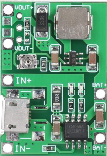
The HW-357 Li-ion Battery Charge Discharge Power Bank Charger Module, manufactured by Sharvi Electronics, is a versatile and compact module designed for charging and discharging lithium-ion batteries. It integrates charging, discharging, and protection functionalities, making it ideal for portable power bank applications and other battery-powered devices. This module is widely used in DIY electronics projects, prototyping, and consumer electronics.
Explore Projects Built with Sharvi electronics


Explore Projects Built with Sharvi electronics
Common Applications
- Power banks for mobile devices
- DIY battery-powered projects
- Portable electronic devices
- Backup power systems
- Wearable technology
Technical Specifications
The HW-357 module is designed to provide efficient and safe charging and discharging of lithium-ion batteries. Below are its key technical details:
| Parameter | Value |
|---|---|
| Input Voltage Range | 5V DC (via micro-USB or solder pads) |
| Charging Current | 1A (default) |
| Battery Type | Single-cell 3.7V Li-ion battery |
| Overcharge Protection | 4.2V ± 1% |
| Over-discharge Protection | 2.5V ± 1% |
| Output Voltage | 5V DC |
| Output Current | 1A (max) |
| Efficiency | Up to 92% |
| Dimensions | 25mm x 19mm x 5mm |
Pin Configuration and Descriptions
The HW-357 module has several pins and connectors for input, output, and battery connections. Below is the pin configuration:
| Pin/Connector | Description |
|---|---|
| Micro-USB Port | Input for 5V DC power supply to charge the battery. |
| BAT+ | Positive terminal for connecting the Li-ion battery. |
| BAT- | Negative terminal for connecting the Li-ion battery. |
| OUT+ | Positive terminal for output voltage (5V DC). |
| OUT- | Negative terminal for output voltage (ground). |
| Solder Pads | Alternative input for 5V DC power supply (if micro-USB is not used). |
Usage Instructions
How to Use the HW-357 Module in a Circuit
- Connect the Battery:
- Connect the positive terminal of the 3.7V Li-ion battery to the
BAT+pin. - Connect the negative terminal of the battery to the
BAT-pin.
- Connect the positive terminal of the 3.7V Li-ion battery to the
- Provide Input Power:
- Use a 5V DC power source (e.g., USB adapter or power supply) and connect it to the micro-USB port or solder pads.
- Connect the Load:
- Attach the load (e.g., a device requiring 5V power) to the
OUT+andOUT-pins.
- Attach the load (e.g., a device requiring 5V power) to the
- Monitor the LEDs:
- The module has built-in indicator LEDs:
- Red LED: Charging in progress.
- Blue LED: Charging complete or discharging in progress.
- The module has built-in indicator LEDs:
Important Considerations and Best Practices
- Ensure the input voltage does not exceed 5.5V to avoid damaging the module.
- Use a single-cell 3.7V Li-ion battery with a capacity of at least 1000mAh for optimal performance.
- Avoid short-circuiting the output terminals (
OUT+andOUT-). - Do not exceed the maximum output current of 1A to prevent overheating or damage.
- If using the module with an Arduino UNO or other microcontroller, ensure the load does not exceed the module's output capacity.
Example: Using HW-357 with Arduino UNO
Below is an example of how to use the HW-357 module to power an Arduino UNO:
- Connect the
OUT+pin of the HW-357 module to the 5V pin of the Arduino UNO. - Connect the
OUT-pin of the HW-357 module to the GND pin of the Arduino UNO. - Ensure the battery is connected to the
BAT+andBAT-pins of the module. - Provide input power to the module via the micro-USB port to charge the battery.
// Example Arduino code to blink an LED using power from the HW-357 module

const int ledPin = 13; // Pin connected to the onboard LED

void setup() {
  pinMode(ledPin, OUTPUT); // Set the LED pin as an output
}

void loop() {
  digitalWrite(ledPin, HIGH); // Turn the LED on
  delay(1000);                // Wait for 1 second
  digitalWrite(ledPin, LOW);  // Turn the LED off
  delay(1000);                // Wait for 1 second
}
Troubleshooting and FAQs
Common Issues and Solutions
Module Overheating:
- Cause: Excessive load current or input voltage above 5.5V.
- Solution: Reduce the load current to below 1A and ensure the input voltage is within the specified range.
Battery Not Charging:
- Cause: Loose connections or faulty battery.
- Solution: Check the connections to the
BAT+andBAT-pins. Replace the battery if necessary.
No Output Voltage:
- Cause: Battery is over-discharged or disconnected.
- Solution: Recharge the battery or reconnect it to the module.
LED Indicators Not Working:
- Cause: Faulty module or incorrect wiring.
- Solution: Verify all connections and replace the module if the issue persists.
FAQs
Can I use this module with a 2-cell Li-ion battery pack?
- No, the HW-357 is designed for single-cell 3.7V Li-ion batteries only.
What happens if the battery voltage drops below 2.5V?
- The module's over-discharge protection will disconnect the battery to prevent damage.
Can I charge the battery and power a load simultaneously?
- Yes, the HW-357 supports simultaneous charging and discharging, but ensure the total current does not exceed 1A.
Is the module compatible with solar panels?
- Yes, as long as the solar panel provides a stable 5V output within the module's input voltage range.
By following this documentation, users can effectively integrate the HW-357 module into their projects and ensure safe and reliable operation.