The TE Connectivity MS4525DO is a digital pressure sensor designed for applications requiring precise measurement of fluid flow velocity. It operates based on the principles of a Pitot tube, which measures the dynamic and static pressure of a fluid to calculate its velocity. This sensor integrates advanced MEMS technology and a digital output, making it ideal for modern electronic systems.
Explore Projects Built with Pitot Tube
Use Cirkit Designer to design, explore, and prototype these projects online. Some projects support real-time simulation. Click "Open Project" to start designing instantly!
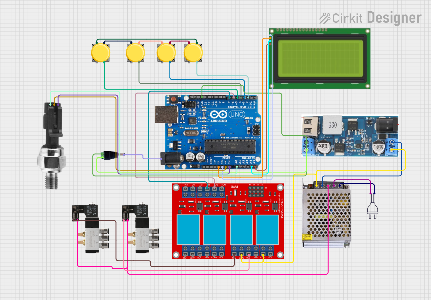
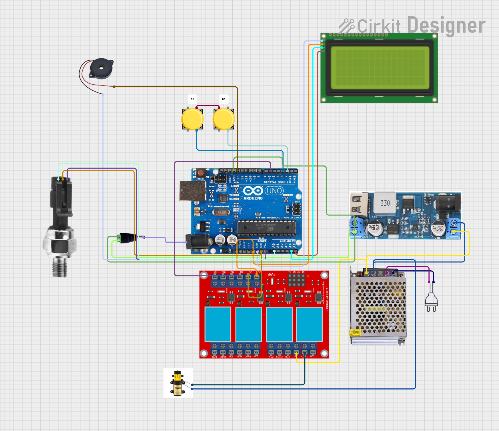
This circuit is an automated tire inflator system controlled by an Arduino Uno. It uses an industrial pressure sensor to monitor tire pressure, an LCD to display information, and a relay module to control a pump and solenoid valves for inflating and purging air. The system includes pushbuttons for user input and a buzzer for alerts.
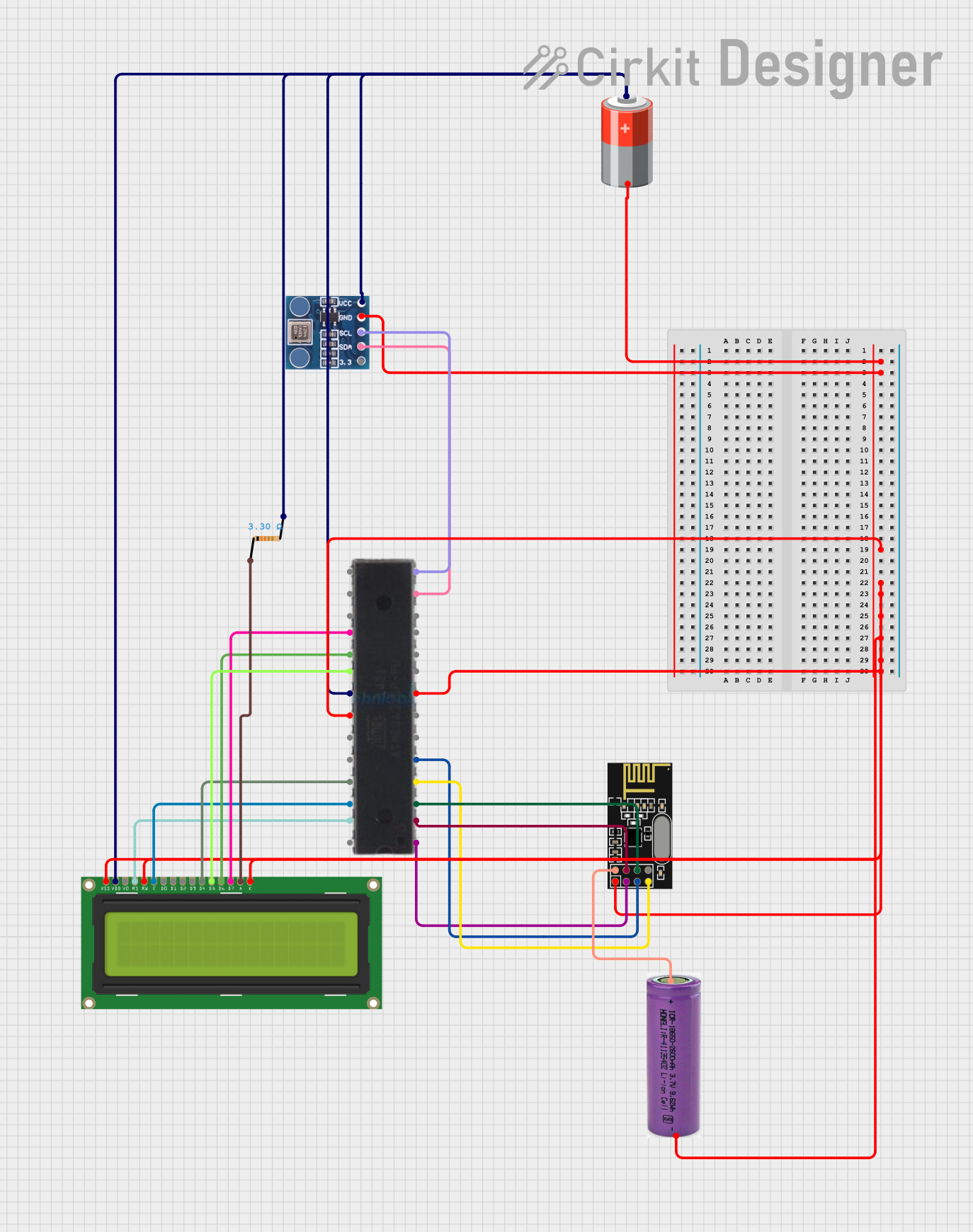
This circuit is designed for a Tire Pressure Monitoring System using an ATmega328P microcontroller. It reads temperature and pressure data from BMP180 sensors, displays the readings on a 16x2 LCD, and transmits the data wirelessly via an NRF24L01 module. The circuit is powered by a 5V battery, with a 3.3V battery specifically for the NRF24L01, and includes a resistor for the LCD backlight.
This circuit is an automated tire inflator system controlled by an Arduino Uno. It uses multiple pushbuttons for user input, an industrial pressure sensor to monitor tire pressure, and a 4-channel relay module to control solenoid valves for inflating and purging air. The system also includes an LCD display for user interface and feedback.
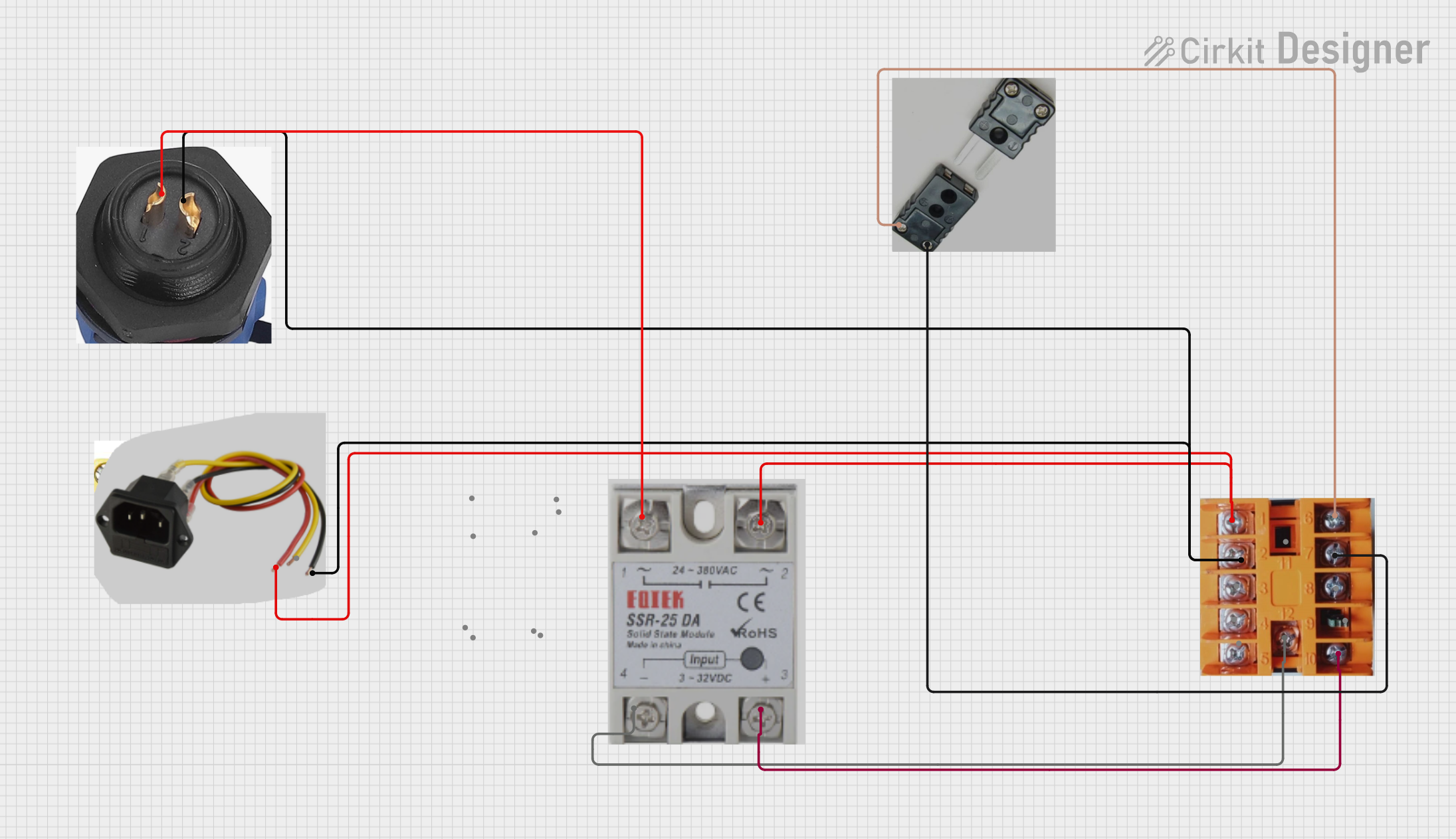
This circuit is a temperature control system that uses a thermocouple to measure temperature and a PID controller to regulate it. The PID controller drives a solid-state relay (SSR) to control an external load, with power supplied through an AC inlet socket.
HVAC: Air velocity monitoring in ventilation systems
Robotics: Environmental sensing for drones and autonomous vehicles
Technical Specifications
The MS4525DO is a high-performance digital pressure sensor with the following key specifications:
General Specifications
Parameter
Value
Manufacturer
TE Connectivity
Part Number
MS4525DO
Pressure Range
±1 psi to ±30 psi (varies by model)
Supply Voltage
3.3V or 5V
Output Type
I²C or SPI (digital)
Accuracy
±0.25% of full scale
Operating Temperature
-40°C to +125°C
Response Time
1 ms
Pin Configuration and Descriptions
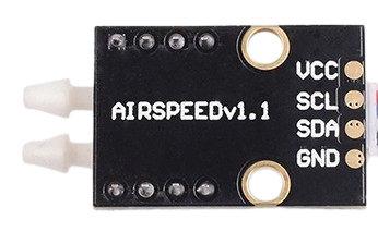
The MS4525DO sensor typically comes in a 6-pin package. Below is the pinout and description:
Pin Number
Pin Name
Description
1
VDD
Power supply (3.3V or 5V)
2
GND
Ground connection
3
SDA
I²C data line (or SPI MOSI)
4
SCL
I²C clock line (or SPI SCK)
5
ADDR/CS
I²C address select (or SPI chip select)
6
NC
No connection (leave unconnected)
Usage Instructions
How to Use the MS4525DO in a Circuit
Power Supply: Connect the VDD pin to a 3.3V or 5V power source and the GND pin to ground.
Communication Interface: Choose between I²C or SPI communication. For I²C:
Connect the SDA pin to the microcontroller's I²C data line.
Connect the SCL pin to the microcontroller's I²C clock line.
Use the ADDR pin to set the I²C address (pull high or low as needed).
For SPI:
Connect the SDA pin to the microcontroller's MOSI line.
Connect the SCL pin to the microcontroller's SCK line.
Use the ADDR/CS pin as the chip select line.
Pressure Ports: Attach the Pitot tube to the sensor's pressure ports:
The high-pressure port (P1) connects to the dynamic pressure source.
The low-pressure port (P2) connects to the static pressure source.
Initialization: Configure the microcontroller to communicate with the sensor using the chosen protocol. Refer to the datasheet for initialization commands.
Important Considerations and Best Practices
Ensure the pressure range of the sensor matches your application requirements.
Avoid exposing the sensor to pressures beyond its rated range to prevent damage.
Use proper tubing and fittings to minimize leaks and ensure accurate measurements.
If using I²C, ensure pull-up resistors are present on the SDA and SCL lines.
Calibrate the sensor periodically for optimal accuracy.
Example Code for Arduino UNO (I²C)
#include <Wire.h>

// Define the I²C address of the MS4525DO sensor
#define MS4525DO_ADDRESS 0x28

void setup() {
  Wire.begin(); // Initialize I²C communication
  Serial.begin(9600); // Start serial communication for debugging
}

void loop() {
  Wire.beginTransmission(MS4525DO_ADDRESS); // Start communication with sensor
  Wire.write(0x00); // Request data from the sensor
  Wire.endTransmission(false); // End transmission but keep I²C active

  Wire.requestFrom(MS4525DO_ADDRESS, 4); // Request 4 bytes of data
  if (Wire.available() == 4) {
    uint8_t byte1 = Wire.read(); // Read first byte
    uint8_t byte2 = Wire.read(); // Read second byte
    uint8_t byte3 = Wire.read(); // Read third byte
    uint8_t byte4 = Wire.read(); // Read fourth byte

    // Combine bytes to calculate pressure and temperature
    int16_t pressure = ((byte1 & 0x3F) << 8) | byte2;
    int16_t temperature = ((byte3 << 8) | byte4) >> 5;

    // Convert raw values to meaningful units
    float pressure_psi = (pressure - 8192) * 0.00390625; // Example conversion
    float temperature_c = (temperature * 0.0977) - 50; // Example conversion

    // Print results to the serial monitor
    Serial.print("Pressure (psi): ");
    Serial.print(pressure_psi);
    Serial.print(" | Temperature (°C): ");
    Serial.println(temperature_c);
  }

  delay(1000); // Wait 1 second before next reading
}
Troubleshooting and FAQs
Common Issues and Solutions
No Data from Sensor
Cause: Incorrect wiring or communication protocol mismatch.
Solution: Double-check the connections and ensure the correct protocol (I²C or SPI) is configured.
Inaccurate Readings
Cause: Calibration drift or leaks in the pressure tubing.
Solution: Recalibrate the sensor and inspect the tubing for leaks.
Sensor Not Responding
Cause: Incorrect power supply voltage.
Solution: Verify that the VDD pin is supplied with 3.3V or 5V as required.
Fluctuating Measurements
Cause: Electrical noise or unstable pressure source.
Solution: Add decoupling capacitors near the sensor and stabilize the pressure source.
FAQs
Q: Can the MS4525DO measure both positive and negative pressures?
A: Yes, the sensor supports differential pressure measurement, allowing it to measure both positive and negative pressures within its specified range.
Q: Is the MS4525DO waterproof?
A: No, the sensor is not waterproof. Avoid exposing it to liquids or high humidity environments.
Q: Can I use the MS4525DO with a 5V microcontroller?
A: Yes, the sensor is compatible with both 3.3V and 5V systems. Ensure the I²C or SPI logic levels match the microcontroller.
Q: How often should I calibrate the sensor?
A: Calibration frequency depends on the application. For critical measurements, calibrate every 6-12 months or as needed.

 Open Project in Cirkit Designer