How to Use Color Sensor: Examples, Pinouts, and Specs
Introduction
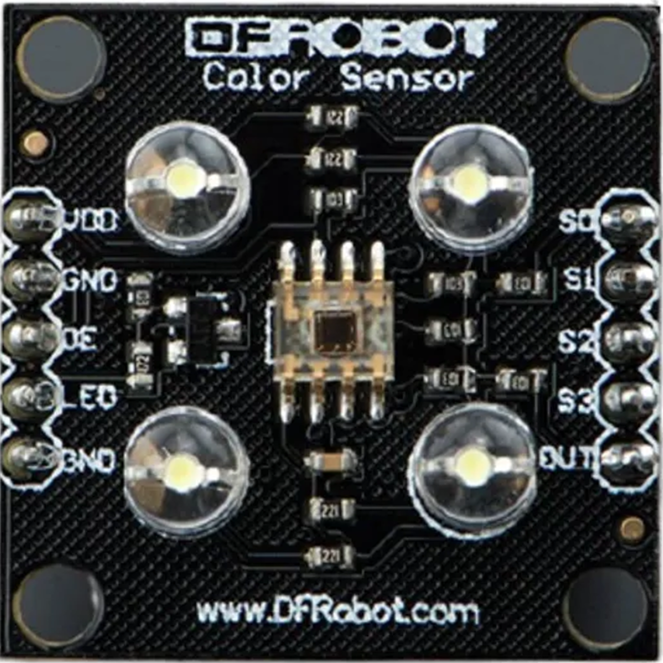
The TCS3200 Color Sensor, manufactured by TAOS, is a highly versatile device designed to detect and measure the color of an object or light source. It achieves this by converting light intensity into frequency signals, which can then be processed by a microcontroller. The sensor is widely used in robotics, automation, and industrial applications for tasks such as color sorting, object recognition, and navigation.
Explore Projects Built with Color Sensor

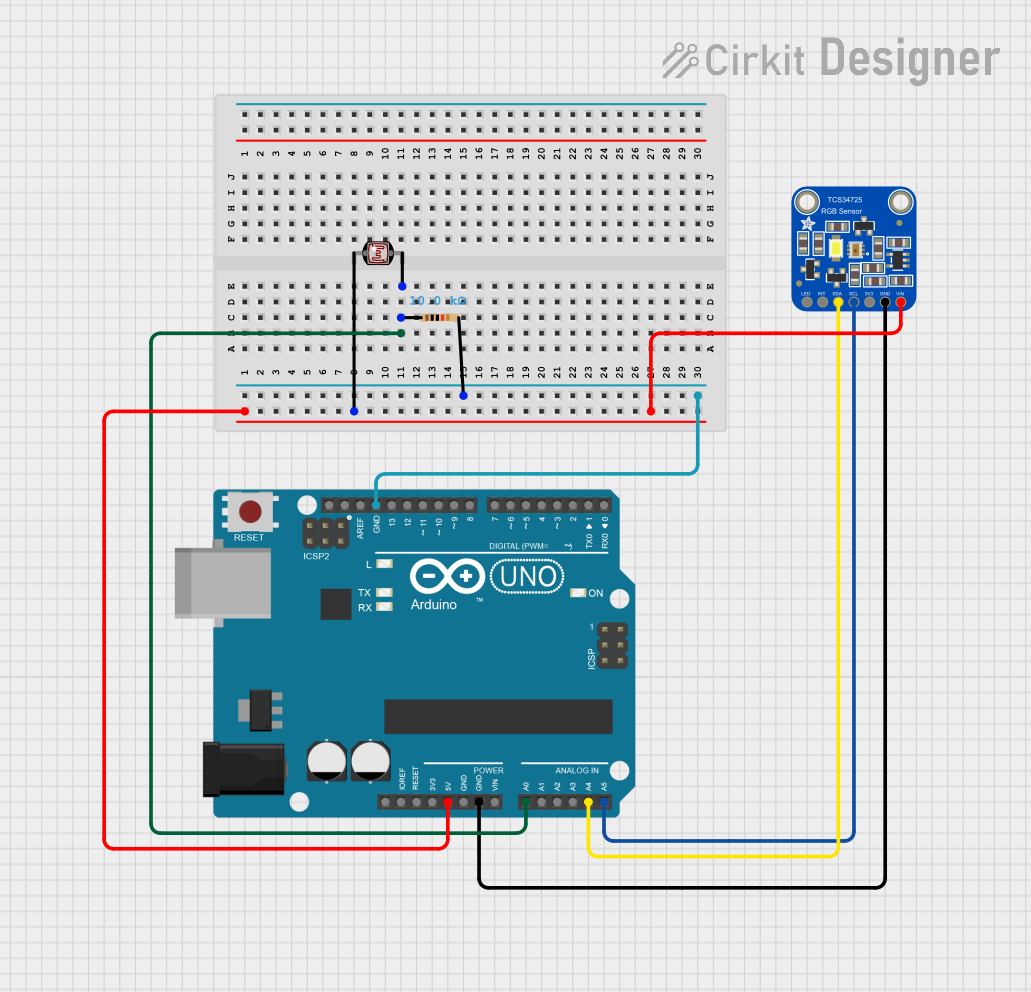
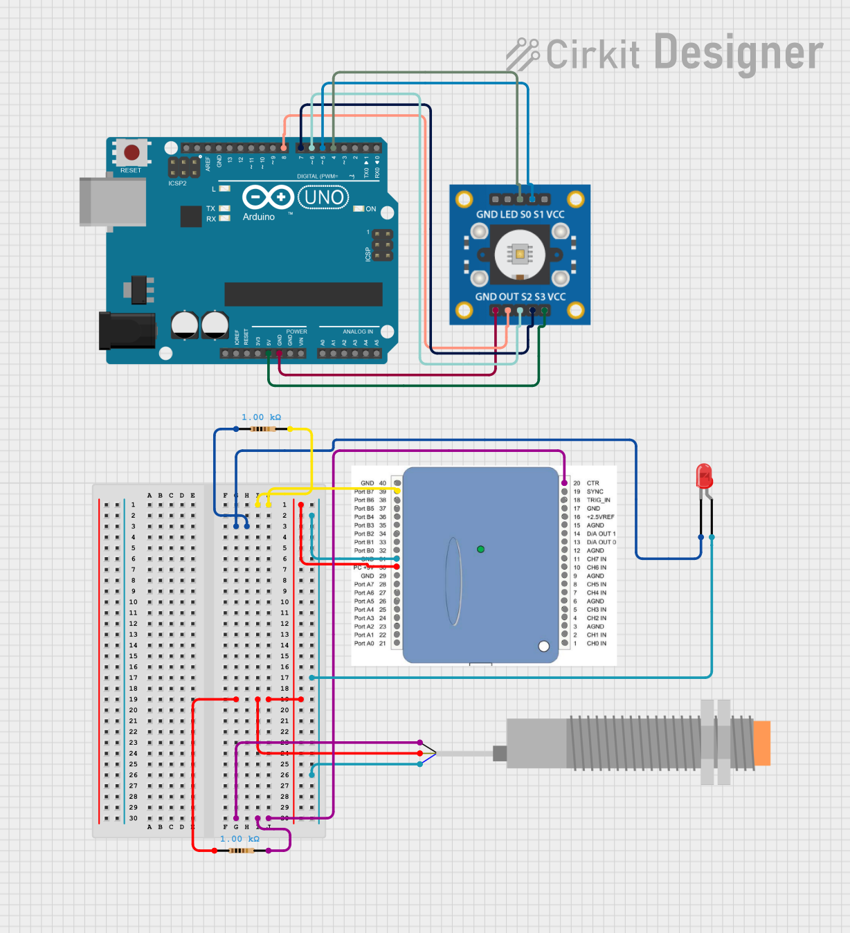
Explore Projects Built with Color Sensor
Common Applications
- Robotics: Identifying colored objects for sorting or navigation.
- Industrial Automation: Color-based quality control and sorting systems.
- Consumer Electronics: Color detection in smart devices.
- Educational Projects: Teaching color recognition and sensor interfacing.
Technical Specifications
The TCS3200 is a programmable color light-to-frequency converter with the following key specifications:
| Parameter | Value |
|---|---|
| Supply Voltage (Vcc) | 2.7V to 5.5V |
| Operating Current | 2mA (typical) |
| Output Frequency Range | 2 Hz to 500 kHz |
| Light Source | White LEDs (integrated on the module) |
| Output Type | Square wave (frequency proportional to light intensity) |
| Operating Temperature | -40°C to +85°C |
Pin Configuration and Descriptions
The TCS3200 module typically has an 8-pin interface. Below is the pin configuration:
| Pin | Name | Description |
|---|---|---|
| 1 | S0 | Output frequency scaling input (control pin) |
| 2 | S1 | Output frequency scaling input (control pin) |
| 3 | S2 | Photodiode type selection input (control pin) |
| 4 | S3 | Photodiode type selection input (control pin) |
| 5 | OUT | Output frequency signal (square wave proportional to light intensity) |
| 6 | GND | Ground connection |
| 7 | OE | Output enable (active low, enables the output when connected to GND) |
| 8 | Vcc | Power supply input (2.7V to 5.5V) |
Usage Instructions
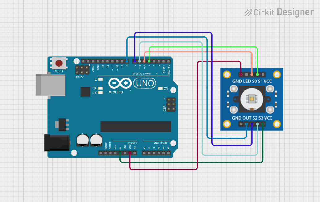
How to Use the TCS3200 in a Circuit
- Power the Sensor: Connect the Vcc pin to a 5V power supply and the GND pin to ground.
- Control Pins: Use the S0 and S1 pins to set the output frequency scaling factor:
- S0 = LOW, S1 = LOW: Power down
- S0 = LOW, S1 = HIGH: 2% scaling
- S0 = HIGH, S1 = LOW: 20% scaling
- S0 = HIGH, S1 = HIGH: 100% scaling
- Photodiode Selection: Use the S2 and S3 pins to select the color filter:
- S2 = LOW, S3 = LOW: Red filter
- S2 = LOW, S3 = HIGH: Blue filter
- S2 = HIGH, S3 = LOW: Clear (no filter)
- S2 = HIGH, S3 = HIGH: Green filter
- Output Signal: Connect the OUT pin to a microcontroller to read the frequency signal. The frequency corresponds to the intensity of the selected color.
Important Considerations
- Ambient Light: Ensure the sensor is shielded from ambient light for accurate readings.
- Scaling Factor: Use the appropriate scaling factor (via S0 and S1) to match the microcontroller's frequency measurement capabilities.
- Output Enable: Keep the OE pin connected to GND to enable the output signal.
Example Code for Arduino UNO
Below is an example of interfacing the TCS3200 with an Arduino UNO to detect colors:
// Pin definitions for TCS3200
#define S0 2  // Connect to S0 pin of TCS3200
#define S1 3  // Connect to S1 pin of TCS3200
#define S2 4  // Connect to S2 pin of TCS3200
#define S3 5  // Connect to S3 pin of TCS3200
#define OUT 6 // Connect to OUT pin of TCS3200

void setup() {
  pinMode(S0, OUTPUT);
  pinMode(S1, OUTPUT);
  pinMode(S2, OUTPUT);
  pinMode(S3, OUTPUT);
  pinMode(OUT, INPUT);

  // Set frequency scaling to 20%
  digitalWrite(S0, HIGH);
  digitalWrite(S1, LOW);

  Serial.begin(9600); // Initialize serial communication
}

void loop() {
  // Select red filter
  digitalWrite(S2, LOW);
  digitalWrite(S3, LOW);
  int redFrequency = pulseIn(OUT, LOW); // Measure frequency for red

  // Select green filter
  digitalWrite(S2, HIGH);
  digitalWrite(S3, HIGH);
  int greenFrequency = pulseIn(OUT, LOW); // Measure frequency for green

  // Select blue filter
  digitalWrite(S2, LOW);
  digitalWrite(S3, HIGH);
  int blueFrequency = pulseIn(OUT, LOW); // Measure frequency for blue

  // Print the measured frequencies
  Serial.print("Red: ");
  Serial.print(redFrequency);
  Serial.print(" Green: ");
  Serial.print(greenFrequency);
  Serial.print(" Blue: ");
  Serial.println(blueFrequency);

  delay(500); // Wait for 500ms before the next reading
}
Troubleshooting and FAQs
Common Issues
No Output Signal:
- Ensure the OE pin is connected to GND to enable the output.
- Verify the power supply voltage is within the specified range (2.7V to 5.5V).
Inaccurate Color Readings:
- Check for ambient light interference and shield the sensor if necessary.
- Ensure the object being measured is close enough to the sensor for accurate detection.
Microcontroller Not Detecting Frequency:
- Verify the scaling factor (S0 and S1 settings) matches the microcontroller's frequency measurement range.
- Check the wiring connections between the sensor and the microcontroller.
FAQs
Q: Can the TCS3200 detect black or white?
A: Yes, the sensor can detect black (low frequency output) and white (high frequency output) based on the intensity of reflected light.
Q: How do I improve accuracy in color detection?
A: Use a consistent light source, shield the sensor from ambient light, and calibrate the sensor for your specific application.
Q: Can I use the TCS3200 with a 3.3V microcontroller?
A: Yes, the TCS3200 operates within a voltage range of 2.7V to 5.5V, making it compatible with 3.3V systems.