
How to Use 0.71inch DualEye LCD Module: Examples, Pinouts, and Specs
 Design with 0.71inch DualEye LCD Module in Cirkit Designer
Introduction
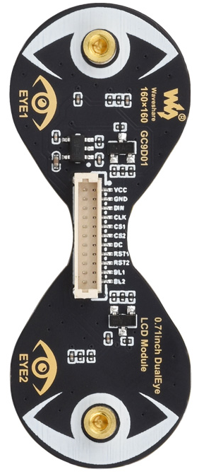
The 0.71inch DualEye LCD Module (Manufacturer Part ID: GC9D01) by Waveshare is a compact display module featuring two independent LCD screens. This module is designed for applications requiring simultaneous visual output on two displays, making it ideal for embedded systems, wearable devices, and other compact electronic projects. Its small size and dual-screen functionality allow for efficient and versatile information display in a variety of use cases.
Explore Projects Built with 0.71inch DualEye LCD Module
 Open Project in Cirkit Designer
 Open Project in Cirkit Designer
 Open Project in Cirkit Designer
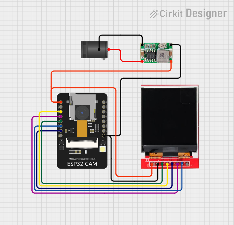 Open Project in Cirkit Designer
Explore Projects Built with 0.71inch DualEye LCD Module
Open Project in Cirkit DesignerOpen Project in Cirkit DesignerOpen Project in Cirkit DesignerOpen Project in Cirkit DesignerCommon Applications
- Wearable devices (e.g., smart glasses, fitness trackers)
- Compact IoT devices
- Robotics and automation systems
- Portable diagnostic tools
- Multi-display dashboards for embedded systems
Technical Specifications
Below are the key technical details of the 0.71inch DualEye LCD Module:
| Parameter | Specification |
|---|---|
| Manufacturer | Waveshare |
| Part ID | GC9D01 |
| Display Type | Dual LCD |
| Screen Size | 0.71 inches (per screen) |
| Resolution | 128 × 32 pixels (per screen) |
| Interface | SPI |
| Operating Voltage | 3.3V |
| Operating Current | ~20mA (typical) |
| Communication Protocol | 4-wire SPI |
| Dimensions | 25mm × 10mm × 2mm |
| Operating Temperature | -20°C to 70°C |
Pin Configuration
The module features a total of 8 pins for power, communication, and control. Below is the pinout description:
| Pin | Name | Description |
|---|---|---|
| 1 | VCC | Power supply input (3.3V) |
| 2 | GND | Ground |
| 3 | DIN | SPI data input (MOSI) |
| 4 | CLK | SPI clock input (SCK) |
| 5 | CS1 | Chip select for LCD1 (active low) |
| 6 | CS2 | Chip select for LCD2 (active low) |
| 7 | DC | Data/Command control pin (High = Data, Low = Command) |
| 8 | RST | Reset pin (active low) |
Usage Instructions
Connecting the Module
To use the 0.71inch DualEye LCD Module in a circuit, follow these steps:
- Power Supply: Connect the
VCCpin to a 3.3V power source and theGNDpin to ground. - SPI Communication: Connect the
DINpin to the MOSI pin of your microcontroller and theCLKpin to the SCK pin. - Chip Select: Use the
CS1andCS2pins to select the respective LCD screen for communication. Only one chip select pin should be active at a time. - Control Pins: Connect the
DCpin to a GPIO pin for toggling between data and command modes. Use theRSTpin to reset the module during initialization.
Example: Using with Arduino UNO
Below is an example of how to interface the module with an Arduino UNO. This example demonstrates displaying text on both screens.
Wiring Diagram
| LCD Module Pin | Arduino UNO Pin |
|---|---|
| VCC | 3.3V |
| GND | GND |
| DIN | D11 (MOSI) |
| CLK | D13 (SCK) |
| CS1 | D9 |
| CS2 | D10 |
| DC | D8 |
| RST | D7 |
Arduino Code
#include <SPI.h>

// Define pin connections
#define CS1 9  // Chip select for LCD1
#define CS2 10 // Chip select for LCD2
#define DC 8   // Data/Command pin
#define RST 7  // Reset pin

void setup() {
  // Initialize SPI communication
  SPI.begin();

  // Configure control pins as outputs
  pinMode(CS1, OUTPUT);
  pinMode(CS2, OUTPUT);
  pinMode(DC, OUTPUT);
  pinMode(RST, OUTPUT);

  // Reset the module
  digitalWrite(RST, LOW);
  delay(10);
  digitalWrite(RST, HIGH);

  // Initialize both screens
  initLCD(CS1);
  initLCD(CS2);
}

void loop() {
  // Display text on LCD1
  selectLCD(CS1);
  displayText("Hello LCD1!");

  // Display text on LCD2
  selectLCD(CS2);
  displayText("Hello LCD2!");

  delay(1000); // Wait for 1 second
}

// Function to initialize an LCD screen
void initLCD(int csPin) {
  digitalWrite(csPin, LOW); // Select the LCD
  // Send initialization commands here
  digitalWrite(csPin, HIGH); // Deselect the LCD
}

// Function to select an LCD screen
void selectLCD(int csPin) {
  digitalWrite(CS1, HIGH); // Deselect LCD1
  digitalWrite(CS2, HIGH); // Deselect LCD2
  digitalWrite(csPin, LOW); // Select the desired LCD
}

// Function to display text on the selected LCD
void displayText(const char* text) {
  digitalWrite(DC, HIGH); // Set to data mode
  // Send text data via SPI
  for (int i = 0; text[i] != '\0'; i++) {
    SPI.transfer(text[i]);
  }
}
Best Practices
- Ensure the module is powered with a stable 3.3V supply to avoid damage.
- Use appropriate pull-up resistors on the SPI lines if required by your microcontroller.
- Avoid activating both
CS1andCS2simultaneously to prevent communication conflicts. - Handle the module carefully to avoid damaging the delicate LCD screens.
Troubleshooting and FAQs
Common Issues
No Display Output
- Ensure the module is powered correctly (check
VCCandGNDconnections). - Verify SPI connections and ensure the correct pins are used.
- Check that the
RSTpin is toggled during initialization.
- Ensure the module is powered correctly (check
Flickering or Corrupted Display
- Ensure only one chip select pin (
CS1orCS2) is active at a time. - Verify the SPI clock speed; it should not exceed the module's specifications.
- Ensure only one chip select pin (
Partial Display on One Screen
- Check the
CS1andCS2connections for proper operation. - Ensure the
DCpin is toggled correctly between data and command modes.
- Check the
FAQs
Q: Can I use this module with a 5V microcontroller?
A: The module operates at 3.3V. If using a 5V microcontroller, level shifters are required for the SPI lines.
Q: Can I display images on the screens?
A: Yes, you can display images by sending the appropriate pixel data via SPI. Ensure the image resolution matches the screen's resolution (128 × 32 pixels).
Q: How do I control the brightness of the screens?
A: The module does not have built-in brightness control. You can adjust the brightness by modifying the backlight circuitry if applicable.
Q: Can I use both screens independently?
A: Yes, the CS1 and CS2 pins allow independent control of each screen.